Phase change heat exchange device

A technology of phase-change heat and heat-exchange medium, applied in heating devices, solar thermal devices, indirect heat exchangers, etc., can solve problems such as pipeline over-temperature damage, pipeline material fatigue damage, poor steam heat conductivity, etc., to achieve Reduce temperature non-uniformity, optimize radial temperature uniformity performance, and avoid pipeline warpage

Inactive Publication Date: 2015-01-28
BEIJING TERASOLAR PHOTOTHERMAL TECH CO LTD
View PDF7 Cites 1 Cited by
  • Summary
  • Abstract
  • Description
  • Claims
  • Application Information

AI Technical Summary

Problems solved by technology

Due to the unstable state of water when boiling in the heating tube, there are problems such as two-phase flow transmission and uneven vaporization pressure in the heat collecting tube, such as water hammer, vibration, and fatigue damage of pipeline materials; in addition, when saturated steam becomes superheated In the steam section, due to the poor thermal conductivity and weak heat absorption capacity of the steam, the pipeline is prone to overheating damage; and when the pipeline is heated unevenly, the temperature difference of the pipe wall is large, and severe bending will occur, causing other losses (such as vacuum sealing Destruction); Moreover, the existing technology still does not solve a series of problems caused by the DSG pipeline without local heating (such as local shadows caused by cloud occlusion in the mirror field), such as water input and steam output flow control, and parameter changes. influences

Method used


Image

  • Phase change heat exchange device
  • Phase change heat exchange device
  • Phase change heat exchange device

Examples


Embodiment Construction

[0040] Specific embodiments of the present invention will be described in detail below with reference to the accompanying drawings.

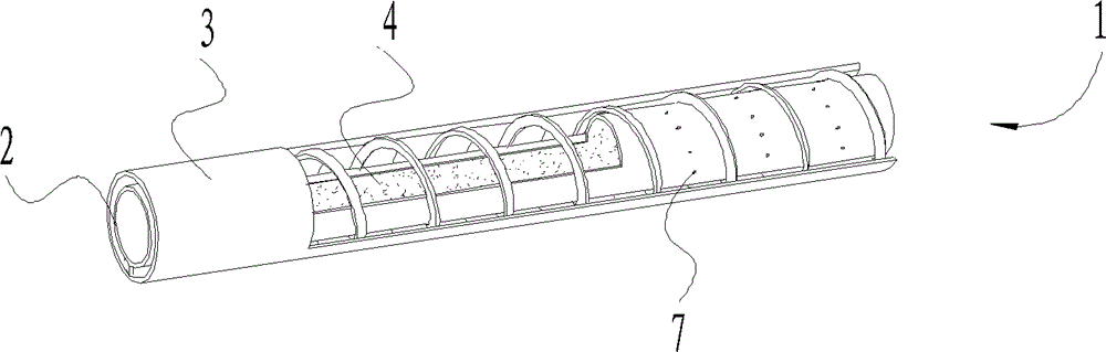
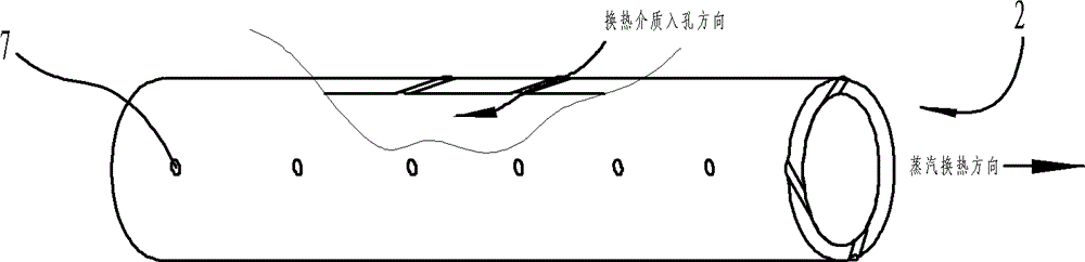
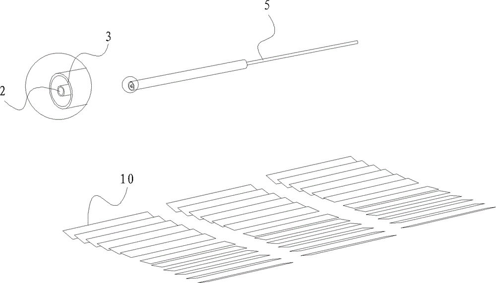
[0041] figure 1 It is a schematic diagram of the first embodiment of the structure of the phase change heat device of the present invention. Fromfigure 1 It can be seen from the partial sectional view that the phase change heat device 1 of the present invention includes a metal inner tube 2 , a metal outer tube 3 and a heat exchange medium 4 . The metal inner tube 2 and the metal outer tube 3 are coaxially arranged inside and outside. The annular space formed by the metal inner tube 2 and the metal outer tube 3 is a liquid phase area, and the inner space of the metal inner tube 2 is a vaporization area.

[0042] On the inside of the tube wall of the metal inner tube 2, a through medium channel is arranged along the axial length direction of the metal inner tube 2, and the medium channel is a capillary through hole 7, a capillary, a nozzle or a...


PUM


Abstract

The invention provides a phase transformation heat exchange device. The device includes an inner tube, an outer tube, and a heat exchange medium; the space between the inner tube and the outer tube forms a whole or a part of a liquid phase region; a whole or a part of space inside the inner tube forms a vaporization region; the heat exchange medium with a relatively high pressure inside the liquid phase region enters the vaporization region with a relatively low pressure while being heated in vortex flow, and flows out of the device after being vapored, so as to complete heat exchange. The device can be applied to DSG systems of the solar energy photo-thermal field, and can also be applied to an input-output system of a heat storage system, or the field of boiler heating. It is achieved with safe operation, low cost, and good application range.

Description

technical field [0001] The invention relates to a heat exchange device applied in multiple fields, in particular to a phase conversion heat exchange device in the field of solar heat utilization. Background technique [0002] With the vigorous development of renewable energy such as solar energy in the world, concentrated solar power (CSP) is gradually recognized by people. In the CSP system, the heat absorption and heat transfer part plays a very important role. The heat exchange medium of solar heat collection technology currently mainly uses heat transfer oil as the heat transfer medium, and after heat exchange through the heat transfer oil, it drives a conventional steam turbine to drive a generator set to generate electricity. Since the current working temperature of heat transfer oil must be controlled within 400°C, exceeding this temperature will lead to problems such as heat transfer oil cracking, increased viscosity, and reduced heat transfer efficiency, which limit...

Claims


Application Information

Patent Timeline
Patent Type & Authority Patents(China)
IPC IPC(8): F28D20/02F24J2/34
CPCF24J2/18Y02E10/41F28D15/04F24J2/07F24J2002/108C09K5/04F24S10/25F24S10/95F24S20/20F24S23/79F24S2023/872F24S2080/05F28F2260/00Y02E10/44F28D15/0266F28D15/043F28D15/046F28D15/06Y02E10/40
Inventor 刘阳
Owner BEIJING TERASOLAR PHOTOTHERMAL TECH CO LTD
Why Eureka
Try Eureka