
Low-inductance and large-power power electronic capacitor

A technology of power electronics and capacitors, which is applied in the field of high-power power electronic capacitors, can solve problems such as large self-inductance of capacitors, thermal breakdown of capacitors, and large parasitic inductance, and achieve the effects of reducing self-inductance, suppressing inductance, and simple structure

Active Publication Date: 2015-06-17
ANHUI TONGFENG ELECTRONICS
View PDF3 Cites 0 Cited by
  • Summary
  • Abstract
  • Description
  • Claims
  • Application Information

AI Technical Summary

Problems solved by technology

When the current of the ripple component passes through the lead-out copper strips, the parasitic inductance generated on the two lead-out copper strips is relatively large, which makes the self-inductance of the capacitor generally relatively large. Generally, its inductance L>60nH, such as in wind power converters The inductance L of the power electronic capacitor is about 100nH. This kind of capacitor is generally only suitable for systems with a switching frequency not exceeding 1500Hz. Otherwise, it will cause local heating at the top of the capacitor and cause serious thermal breakdown of the capacitor.

Method used


Image

  • Low-inductance and large-power power electronic capacitor
  • Low-inductance and large-power power electronic capacitor
  • Low-inductance and large-power power electronic capacitor

Examples


Embodiment Construction

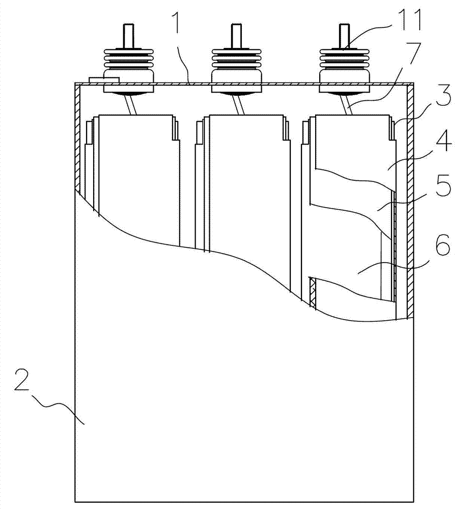
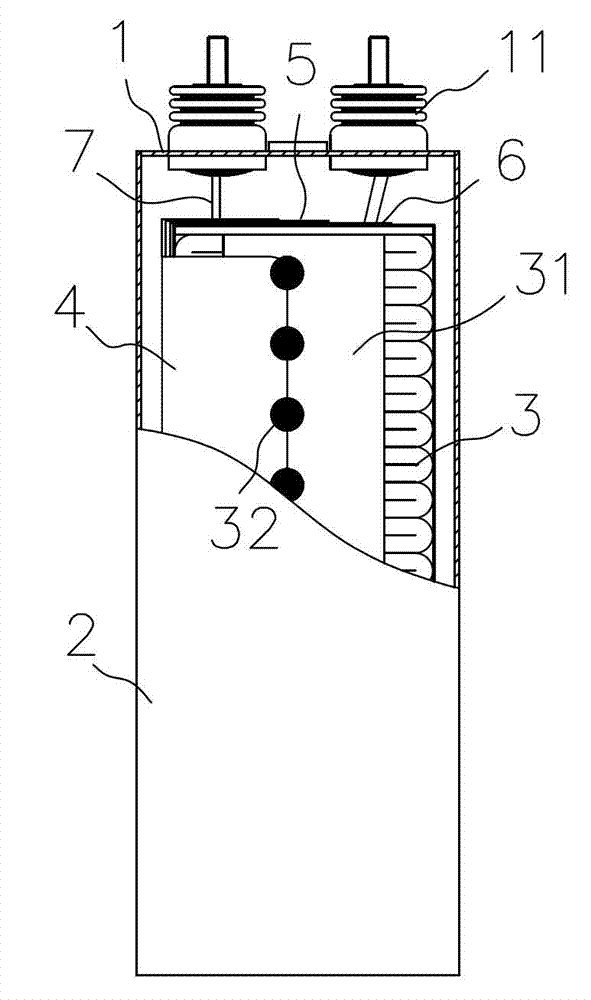
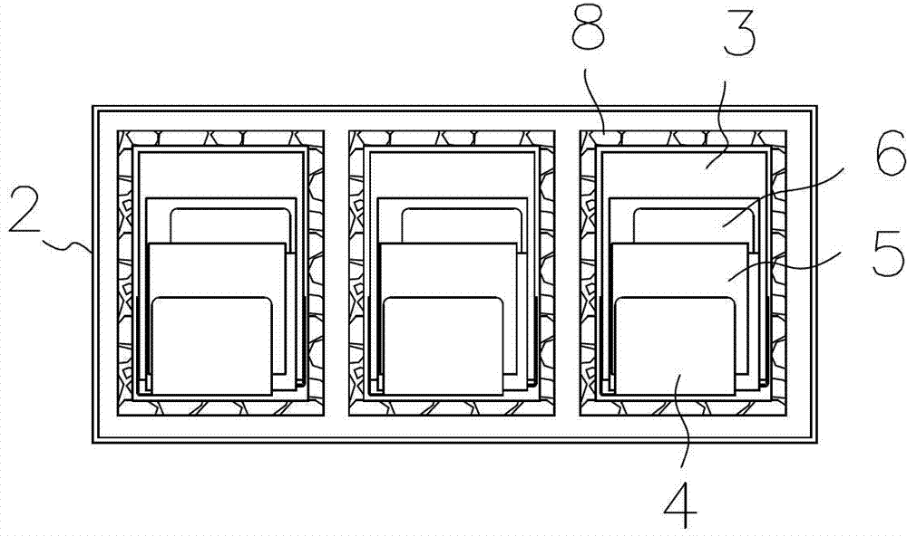
[0013] Such as figure 1 , figure 2 and image 3 As shown, the present invention includes a cover plate assembly 1 , a casing 2 and a capacitor core group 3 . The capacitor core group can be a multi-core group or a single-core group. In this example, the capacitor core group 3 has three groups. The capacitor core group 3 is fixed in the insulating groove 8 at the bottom of the shell 2. The gold surface 31 is electrically connected with lead copper strips 4, 6 used as positive and negative electrodes respectively, figure 2 The middle solder joint 32 is between the lead copper strip 4 and the gold-sprayed surface 31 .

[0014] Lead out copper strip structure such as Figure 4 shown. The two lead-out copper strips 4, 6 respectively include gold-sprayed surface connection parts 41, 61 electrically connected to the gold-sprayed surface 31 of the capacitor core group, and are arranged on the top of the capacitor core group 3 for electrical connection with the lead-out terminal...


PUM


Abstract

The invention relates to a low-inductance and large-power power electronic capacitor which comprises a cover plate assembly, a casing, a capacitor core group and extraction copper straps of the capacitor core group. Each extraction copper strap at least comprises a metal spraying surface connection portion, a terminal connection portion and a middle conduction band, and the middle conduction bands and the terminal connection portion of the two extraction copper straps are at least partially overlapped. The built-in terminal connection portions are at least partially exposed out. An insulation layer is arranged between the middle conduction bands and the terminal connection portions of the two extraction copper straps. Corrugated current and parasitic inductance generated by the middle conduction bands and the terminal connection portions are offset so that the capacitor self inductance can be reduced, and the low-inductance and large-power power electronic capacitor is simple in structure.

Description

technical field [0001] The invention relates to a high-power power electronic capacitor, in particular to a low-inductance high-power power electronic capacitor. Background technique [0002] In the high-power power electronic capacitors commonly used in the market at present, the capacitor core group adopts non-inductive winding, and the self-inductance of each core group is extremely small, so the self-inductance of the capacitor is mainly determined by the self-inductance of the lead-out copper strip. The lower end of the lead-out copper strip is usually welded on the gold-sprayed surface of the capacitor core group, and the upper end is bent horizontally to weld the wire electrically connected to the lead-out terminal of the cover plate assembly. When the current of the ripple component passes through the lead-out copper strips, the parasitic inductance generated on the two lead-out copper strips is relatively large, which makes the self-inductance of the capacitor gener...

Claims


Application Information

Patent Timeline
Patent Type & Authority Patents(China)
IPC IPC(8): H01G4/228
Inventor 杨波黄云锴汪威潘焱尧
Owner ANHUI TONGFENG ELECTRONICS
Learn More