
A trapezoidal cross-section separated transformer

A trapezoidal section, separate technology, applied in the direction of transformer/inductor core, transformer/inductor parts, transformer/inductor coil/winding/connection, etc., can solve the problem of high core utilization, low coupling coefficient, The problem of high coupling coefficient can achieve the effect of improving coupling coefficient, uniform magnetic field distribution, and reducing self-inductance

Active Publication Date: 2018-08-17
INST OF ELECTRICAL ENG CHINESE ACAD OF SCI
View PDF7 Cites 0 Cited by
  • Summary
  • Abstract
  • Description
  • Claims
  • Application Information

AI Technical Summary

Problems solved by technology

[0005] The purpose of the present invention is to overcome the defect of low coupling coefficient between the primary coil and the secondary coil in the existing non-contact power supply system, and propose a separate transformer with trapezoidal cross-section, which has high coupling coefficient and high utilization rate of magnetic core , especially suitable for non-contact power supply systems in the mobile field

Method used


Image

  • A trapezoidal cross-section separated transformer
  • A trapezoidal cross-section separated transformer
  • A trapezoidal cross-section separated transformer

Examples


Embodiment 1

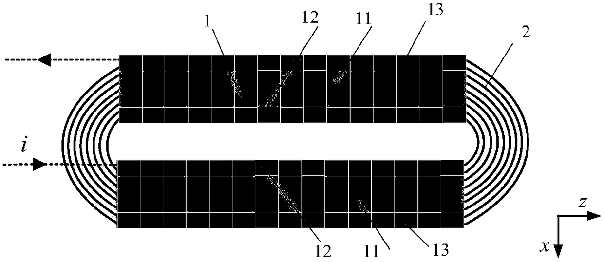
[0033] The two-dimensional section of Example 1 of the present invention is as follows Figure 1a shown. The inner surface 12 and the outer surface 13 of the secondary magnetic core 1 are inclined outward, and the inner surface 12 and the outer surface 13 are connected to the bottom surface 11 of the magnetic core 1 at an obtuse angle. The cross section of the secondary magnetic core 1 is trapezoidal, the inner surface 12 and the outer surface 13 of the secondary magnetic core 1 and the bottom surface 11 of the secondary magnetic core 1 enclose a trapezoidal groove, and the secondary coil 2 is wound on the secondary magnetic core 1 In the groove, the coil is wound in 5 layers. The primary coil 3 is placed on the window side of the secondary magnetic core 1, and connected in the forward direction to form a loop. The winding method of the secondary coil 2 is as follows: Figure 1b As shown, the coil wires are connected in the forward direction. The secondary magnetic cores 1...

Embodiment 2

[0041] The two-dimensional section of Example 2 of the present invention is as follows Figure 2a As shown, looking down as Figure 2b As shown, the secondary core is at Figure 2b The z-axis direction is equally spaced and sparsely arranged, wherein the arrangement interval is equal to the width of the magnetic core in the z-axis direction. In the case that the primary and secondary coil diameters, number of turns and air gap length of the trapezoidal cross-section separated transformer are the same, only the arrangement interval of the secondary magnetic core is changed. In the case where the secondary magnetic cores are arranged at equal intervals, when the magnetic core arrangement interval does not exceed the magnetic core width, the coupling coefficient of the separated transformer in embodiment 2 is the same as that of embodiment 1 in which the secondary magnetic cores are densely arranged The difference is not big, but the amount of magnetic core is reduced, the loss...

Embodiment 3

[0043] The cross section of embodiment 3 of the present invention is as image 3 shown. Embodiment 3 is composed of the bottom surface 21 of the secondary magnetic core, the inner surface 22 of the secondary magnetic core, the outer surface 21 of the secondary magnetic core, the secondary coil 2 and the primary coil 3 . The number of turns of the secondary coil in Example 3 is the same as the number of turns of the secondary coil in Example 1 and Example 2, the secondary coil is laid in 3 layers, and the trapezoidal secondary is flatter.


PUM


Abstract

A separated-type transformer with a trapezoid cross section comprises a secondary magnetic core, a secondary coil and a primary coil, wherein the inner and outer side faces of the secondary magnetic core and the bottom face of the secondary magnetic core form a trapezoid groove through enclosing, and the secondary coil is placed in the trapezoid groove; and the primary coil is placed on a window side of the secondary magnetic core. The secondary coil in the trapezoid groove is spread in a flattened manner; a winding of the secondary coil has a trapezoid cross section; and the number of windings of the secondary coil winding close to the side of the primary coil is larger than the number of windings remote from the primary coil. The included angle between the inner side face of the secondary magnetic core and the magnetic core bottom face, as well as the included angle between the outer side face and the magnetic core bottom face are obtuse angles, wherein the distance between each winding of secondary coil and the primary coil arranged in the trapezoid groove is small due to sizes of the obtuse angles. Under the same number of coil windings, the flattened coil can effectively reduce self-inductance of the coil, increase coupling magnetic flux between primary and secondary coils and increase a coupling coefficient of the separated-type transformer, so that the flattened coil is especially suitable for movable non-contact electric energy transmission.

Description

technical field [0001] The invention relates to a separated transformer structure, in particular to a separated transformer structure used in a non-contact power transmission system in the field of mobile power supply. Background technique [0002] Non-contact power supply is a new power supply mode based on electromagnetic coupling to realize wireless power transmission. It uses the primary coil and secondary coil of a completely separated transformer to realize power transmission through the coupling of high-frequency magnetic field. In the process of power transmission, there is no physical connection between the primary coil on the power supply side and the secondary coil on the power receiving side. Compared with traditional power supply methods, non-contact power supply is convenient and safe to use, without contact loss and risk of electric shock, and without frictional carbon deposition And corresponding maintenance problems, can adapt to a variety of harsh weather a...

Claims


Application Information

Patent Timeline
Patent Type & Authority Patents(China)
IPC IPC(8): H01F27/24H01F27/30
CPCH01F27/24H01F27/306
Inventor 史黎明徐罗那杜玉梅李耀华
Owner INST OF ELECTRICAL ENG CHINESE ACAD OF SCI
Learn More