Method of making thin film solar cells

A technology of solar cells and manufacturing methods, applied in circuits, electrical components, semiconductor devices, etc., can solve problems such as inability to improve reflectivity, high scattering loss, plasma loss, and equipment cost increase, so as to increase photoelectric conversion efficiency and improve process efficiency , The effect of reducing the process cost

Active Publication Date: 2016-12-14
IND TECH RES INST
View PDF6 Cites 0 Cited by
  • Summary
  • Abstract
  • Description
  • Claims
  • Application Information

AI Technical Summary

Problems solved by technology

[0004] However, the implementation of vacuum sputtering technology requires the use of very expensive vacuum sputtering equipment, which leads to a substantial increase in equipment costs for manufacturers, and also leads to the inability to effectively reduce the overall cost of thin-film solar cells.
In addition, on the whole, the optimal forming temperature of thin-film solar cells should not exceed 150 degrees Celsius to avoid damage to the components by high temperatures. However, the existing vacuum sputtering equipment is often accompanied by operating temperatures as high as 200 degrees Celsius. Therefore , which directly affects the overall product yield of thin-film solar cells
Moreover, since the current second electrode layer 13 is mostly equipped with silver electrodes, the arrangement of the silver electrodes cannot avoid the Surface Plasmon Absorption effect that affects the reflective effect, and under the premise that the reflective effect is affected, thin-film solar The overall power generation efficiency of the battery is still not ideal
[0005] In addition, although China Taiwan Patent No. 201119048A1 discloses the technology of using conductive ink fillers as the back electrodes of thin-film solar cells, the size of the conductive ink fillers is designed to be between 0.5nm and 300nm, so it still has Serious problems such as high scattering loss and unavoidable loss of surface plasmons that absorb short wavelengths lead to the inability to improve reflectivity

Method used


Image

  • Method of making thin film solar cells
  • Method of making thin film solar cells
  • Method of making thin film solar cells

Examples


Embodiment Construction

[0026] The implementation of the present invention will be described below through specific examples, and those skilled in the art can easily understand other advantages and effects of the present invention from the content disclosed in this specification. Of course, the present invention can also be implemented or applied through other different specific embodiments.

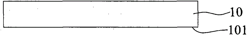
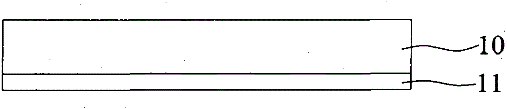
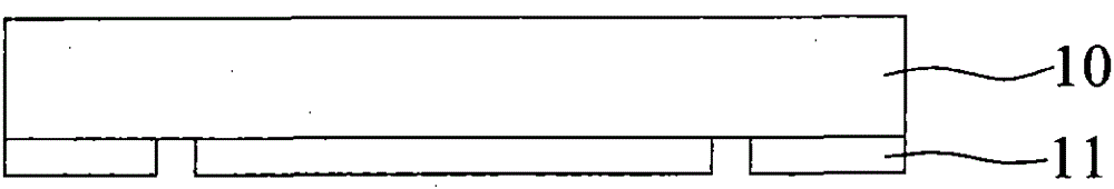
[0027] see Figure 2A to Figure 2E The schematic flow chart shown is to understand the method of manufacturing the thin-film solar cell provided by the present invention. It should be explained first that the method of manufacturing the thin-film solar cell provided by the present invention uses a glass substrate 20 as the base, thereby sequentially forming the first electrode layer 21. The photoelectric conversion layer 22 and the second electrode layer 23.

[0028] In actual implementation, first as Figure 2A , Figure 2B As shown, first provide a glass substrate 20 with a backlight surface 200, and form ...


PUM


Abstract

The invention discloses a method for manufacturing a thin-film solar cell. A light-transmitting first electrode layer is formed on the backlight surface of a glass substrate, and a plurality of first openings are formed on the first electrode layer, so that the first openings The hole exposes part of the backlight surface; then a photoelectric conversion layer is formed on the first electrode layer and the exposed part of the backlight surface, and a plurality of second openings are formed in the photoelectric conversion layer to expose part of the second opening the first electrode layer; and on the photoelectric conversion layer and the exposed part of the first electrode layer by a non-vacuum coating method, a second electrode layer for reflecting light and having a plurality of third openings is formed, the second electrode The layer consists of a conductive gel composed of a polymeric substrate with a non-diffractive filler.

Description

technical field [0001] The invention relates to a method for manufacturing a thin-film solar cell, in particular to a method for manufacturing a thin-film solar cell with a reflective back electrode layer. Background technique [0002] Existing thin-film solar cell manufacturing processes, such as Figure 1A to Figure 1G As shown, a first electrode layer 11, such as a TCO film, is plated on the backlight surface 101 of the glass substrate 10 by vacuum sputtering technology, and then patterned on the first electrode layer 11 by using laser patterning technology. Part of the backlight surface 101 is exposed in the formed patterned opening. [0003] After the step of patterning the first electrode layer 11 is completed, vacuum sputtering technology (or vacuum sputtering method) is used on the first electrode layer 11 and the backlight surface 101 exposed in the patterned opening. A photoelectric conversion layer 12 such as a silicon film is plated, and then patterned on the ph...

Claims


Application Information

Patent Timeline
Patent Type & Authority Patents(China)
IPC IPC(8): H01L31/18
Inventor 刘俊岑陈玉鸿吴建良陈毓儒王裕铭
Owner IND TECH RES INST
Why Eureka
Try Eureka