Multi-level direct current transformation power supply device

A technology of DC conversion and power supply device, applied in the direction of DC network circuit device, parallel operation of DC power supply, circuit device, etc., can solve the problems of capacity reduction, difficulty in meeting, shortened life, etc., to improve stability and reliability, improve design Difficulty, long service life

Inactive Publication Date: 2013-04-03
DALIAN POWER SUPPLY COMPANY STATE GRID LIAONING ELECTRIC POWER +1
View PDF5 Cites 4 Cited by
  • Summary
  • Abstract
  • Description
  • Claims
  • Application Information

AI Technical Summary

Problems solved by technology

[0002] The station power supply of existing smart substations generally adopts AC-DC integrated power supply, and the energy storage device of AC-DC integrated power supply adopts maintenance-free lead-acid batteries. The disadvantages are: 1. To ensure the reliability of use, frequent Monitor the voltage and internal resistance of the battery; 2. The battery has only about 1,000 cycles of charging and discharging life, which is difficult to meet the needs of power supplies such as smart switches and smart terminals in today's smart substations; 3. Undervoltage protection needs to be set when the battery pack is discharged , otherwise the battery will be damaged due to over-discharge, so part of the electric energy of the battery cannot be released and cannot be used effectively, and after a long time of use, the battery will have a memory effect, the capacity will decrease, and the life will be shortened
4. The lead plate of the battery is easy to lose and become thin during the charging and discharging process, and the conversion efficiency of electric energy and chemical energy is reduced
6. The volatilization of acidic liquids affects the environment, and discarded batteries can also bring great harm to the environment

Method used


Image

  • Multi-level direct current transformation power supply device

Examples


Embodiment Construction

[0010] The present invention will be further described below in conjunction with accompanying drawing:

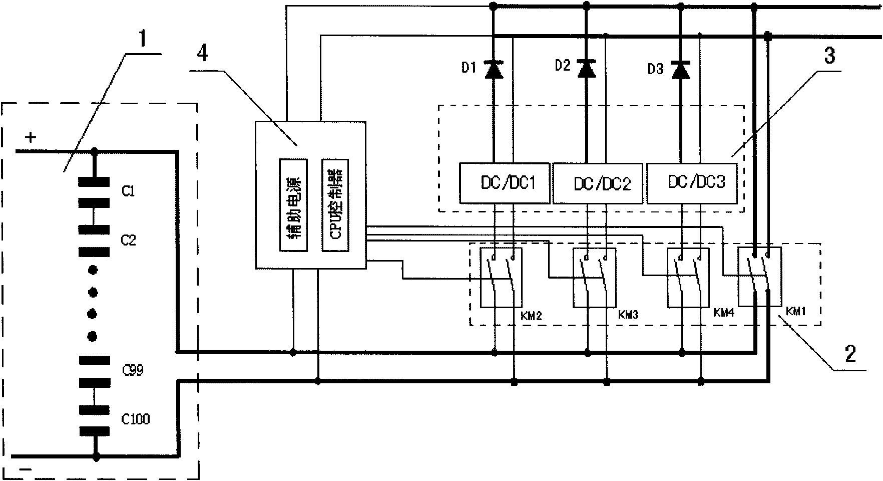
[0011] As shown in the figure, several groups of supercapacitors 1 can be set up, and this embodiment provides one group, with a total of 100 connected in series. Its total output is respectively connected to the input terminals of the four DC contactors in the circuit switching unit 2 . The output terminal of the DC contactor KM1 in the circuit switching unit is directly connected to the load, the output terminal of the DC contactor KM2 is connected to the input terminal of the module DC / DC1 in the multi-stage voltage conversion unit 3; the output terminal of the DC contactor KM3 is connected to the The input terminal of the module DC / DC2 in the multi-level voltage conversion unit is connected; the output terminal of the DC contactor KM4 is connected with the input terminal of the module DC / DC3 in the multi-level voltage conversion unit. The multi-level voltage conversion...


PUM


Abstract

The invention relates to a multi-level direct current transformation power supply device. The multi-level direct current transformation power supply device is characterized by comprising a super capacitor, a circuit switching unit, a multi-level voltage converter unit and a voltage monitoring unit, wherein the total output of the super capacitor is connected with the multi-level voltage converter unit through the circuit switching unit, the multi-level voltage converter unit is connected with a load, the voltage monitoring unit is connected with the output end of the super capacitor and the circuit switching unit and is used for detecting the output voltage of the super capacitor and controlling the motion of the switching unit of a control circuit. The multi-level direct current transformation power supply device provided by the invention adopts a multi-level direct current transformation device, the input voltage can be input in the rang of 50-270 V at will, the stableness and non-interval output of voltage are realized, and stability and reliability are improved; and the multi-level direct current transformation power supply device meets power source requirements of intelligent transformer substations, especially power supply backup decay of a movement intelligent transformer substation, an intelligent on-off action and background monitoring; and the structure is simple, and the service life is long.

Description

technical field [0001] The invention relates to an AC-DC integrated power supply device, in particular to a multi-stage DC conversion power supply device. Background technique [0002] The station power supply of existing smart substations generally adopts AC-DC integrated power supply, and the energy storage device of AC-DC integrated power supply adopts maintenance-free lead-acid batteries. The disadvantages are: 1. To ensure the reliability of use, frequent Monitor the voltage and internal resistance of the battery; 2. The battery has only about 1,000 cycles of charging and discharging life, which is difficult to meet the needs of power supplies such as smart switches and smart terminals in today's smart substations; 3. Undervoltage protection needs to be set when the battery pack is discharged , otherwise the battery will be damaged due to over-discharge, so part of the electric energy of the battery cannot be released and cannot be used effectively, and after a long tim...

Claims


Application Information

Patent Timeline
Patent Type & Authority Applications(China)
IPC IPC(8): H02J11/00H02J7/00H02J1/10
CPCH02J9/06H02J1/108
Inventor 马西田王严军林春清金永辉王田利许立功石洪晶
Owner DALIAN POWER SUPPLY COMPANY STATE GRID LIAONING ELECTRIC POWER
Why Eureka
Try Eureka