Coated antenna device

An antenna device and cladding technology, which is applied in the directions of antenna coupling and radiating element structure, can solve problems such as high side lobe level, adjacent channel interference, and main lobe beam width, so as to solve adjacent channel interference, increase gain, The effect of suppressing sidelobes

Inactive Publication Date: 2015-03-25
骆柳春
View PDF3 Cites 4 Cited by
  • Summary
  • Abstract
  • Description
  • Claims
  • Application Information

AI Technical Summary

Problems solved by technology

However, the use of microstrip arrays not only requires the design of a complex feed network, but also has a wider main lobe beam and higher side lobe levels, which can easily cause adjacent channel interference.

Method used


Image

  • Coated antenna device
  • Coated antenna device
  • Coated antenna device

Examples


Embodiment Construction

[0021] The technical solutions in the embodiments of the present invention will be clearly and completely described below with reference to the accompanying drawings in the embodiments of the present invention. Obviously, the described embodiments are only a part of the embodiments of the present invention, but not all of the embodiments. Based on the embodiments of the present invention, all other embodiments obtained by those of ordinary skill in the art without creative efforts shall fall within the protection scope of the present invention.

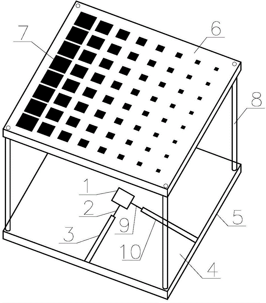
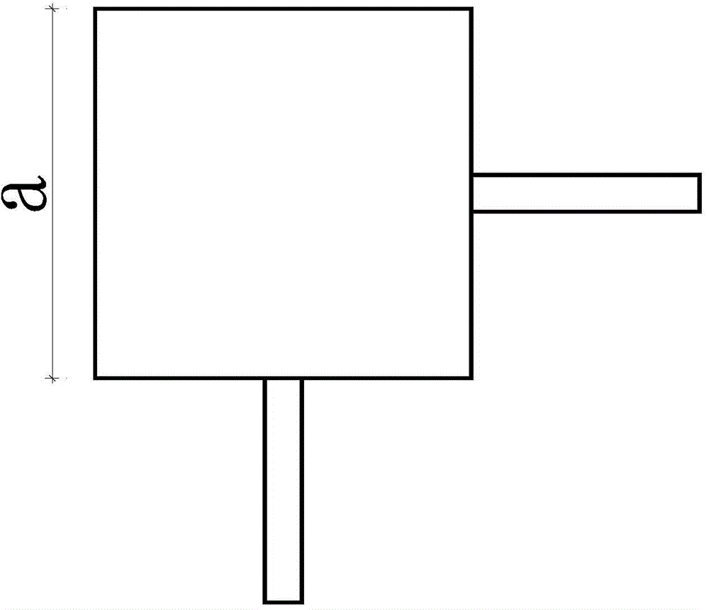
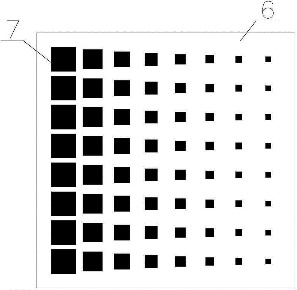
[0022] see Figure 1-3 , the structure of the embodiment of the cladding antenna device provided by the present invention will be described in detail.

[0023] see figure 1 , a schematic diagram of the overall structure of an embodiment of the cladding antenna device provided by the present invention, including a circularly polarized radiation patch 1, an impedance transformation line 2, an impedance transformation line 9, a microstr...


PUM


Abstract

The invention discloses a coated antenna device. The coated antenna device comprises a circular polarization radiation paster, impedance conversion lines, a micro-strip feeder line, a dielectric substrate, an earth plate and a frequency selective surface coating. The circular polarization radiation paster is arranged in the center of the upper surface of the dielectric substrate in an etching mode and connected with the micro-strip feeder line through the impedance conversion lines. The earth plate is arranged on the lower surface of the dielectric substrate in an etching mode, and the frequency selective surface coating is located over the circular polarization radiation paster. The length of the edge of the square circular polarization radiation paster ranges from 13 mm to 15.5 mm, the paster is connected with the two impedance conversion lines, and the joints of the paster and the two impedance conversion lines are located on the different edges of the paster. Sixty-four square metal units are arranged on the lower surface of the frequency selective surface coating in an etching mode and are evenly distributed in an 8*8 array mode, and the area of the square metal units in each line gradually becomes small. According to the coated antenna device, the gain of an antenna can be improved, the sidelobe of the antenna can be reduced, and the performance of the antenna can be improved.

Description

technical field [0001] The present invention relates to the technical field of antennas, and in particular, to a cladding antenna device. Background technique [0002] Electronic toll collection system (ETC, Electronic Toll Collection) is an advanced system composed of high-tech equipment and software such as wireless communication technology, automatic identification technology, image processing technology, computer network technology, etc. Road tolls are charged. [0003] The ETC system consists of roadside reading and writing equipment RSU, on-board unit OBU, ground sensing coil, automatic barrier machine, vehicle detector, fee display, and audit system. The ETC system is a system that communicates and exchanges information with the on-board unit through the roadside unit to achieve automatic identification of the vehicle, and automatically deduct the toll from the user's dedicated account, thereby realizing automatic charging. The basic process of the ETC system is: se...

Claims


Application Information

Patent Timeline
Patent Type & Authority Applications(China)
IPC IPC(8): H01Q1/36H01Q1/38H01Q1/52
Inventor 骆柳春
Owner 骆柳春
Why Eureka
Try Eureka