Azimuth-drive motor system structure of heavy load inertially stabilized platform

An inertial stable platform and system structure technology, applied in the field of azimuth motor system structure of a large-load inertial stable platform, can solve the problems of increased mass of the large-load inertial stable platform, inability to realize direct drive fine-tuning of attitude, and difficulty in further improving accuracy, etc. It can adapt to a wide range of temperature changes and achieve high-precision control, reduce the unilateral magnetic pull and cogging torque fluctuations, and improve the utilization rate.

Inactive Publication Date: 2014-12-17
BEIHANG UNIV
View PDF4 Cites 0 Cited by
  • Summary
  • Abstract
  • Description
  • Claims
  • Application Information

AI Technical Summary

Problems solved by technology

[0003] In the existing aviation inertial stabilization platform design, however, there are many deficiencies in the existing inertial stabilization platform, which are generally manifested as systematic deficiencies in the aspects of large volume, small load / weight ratio, poor precision, etc., that is, it is difficult to find the A product with advantages
Among them, the drive and transmission in the azimuth direction are particularly critical. The current azimuth is mostly operated indirectly by one-stage gear transmission, which increases the mass of the large-load inertial stable platform and makes it impossible to achieve direct drive fine-tuning of the attitude, making it difficult to further improve its accuracy.

Method used


Image

  • Azimuth-drive motor system structure of heavy load inertially stabilized platform
  • Azimuth-drive motor system structure of heavy load inertially stabilized platform
  • Azimuth-drive motor system structure of heavy load inertially stabilized platform

Examples


Embodiment Construction

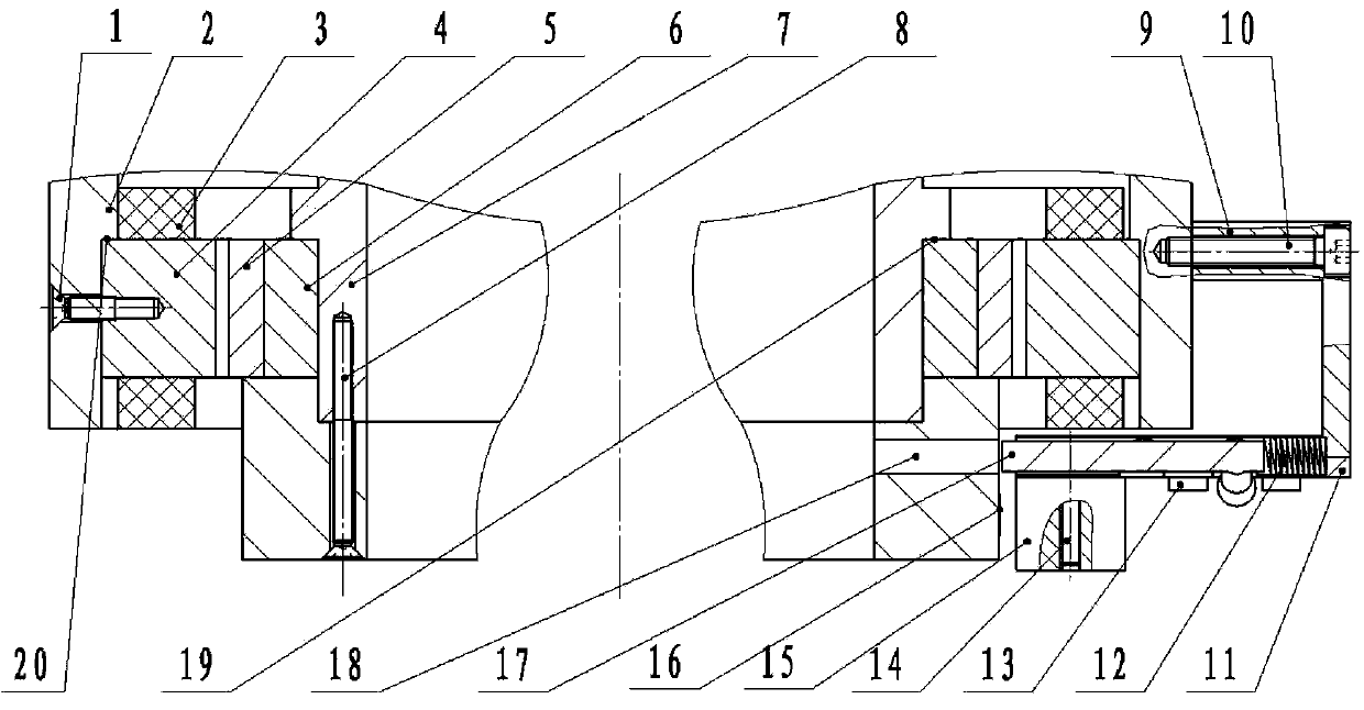
[0029] as attached figure 1 Shown, the present invention is fixed countersunk head screw 1 by stator, motor stator seat 2, stator coil 3, motor stator 4, permanent magnet 5, motor rotor 6, motor rotor seat 7, cover plate fastening countersunk screw 8, reading Head installation transition plate 9, transition plate fastening hexagon socket head screw 10, reading head mounting plate 11, spring 12, reading head mounting plate fastening hexagon socket head screw 13, reading head fixing countersunk head screw 14, grating reading head 15, grating Chi 16, latch 17, motor rotor cover plate 18. Stator fixing countersunk head screw 1, motor stator seat 2, stator coil 3, motor stator 4, permanent magnet 5, motor rotor 6, motor rotor seat 7, and motor rotor cover plate 18 constitute the structural part of the azimuth motor body; Countersunk screw 8, reading head mounting transition plate 9, transition plate fastening hexagon socket head screw 10, reading head mounting plate 11, reading he...


PUM


Abstract

An azimuth-drive motor system structure of a heavy load inertially stabilized platform comprises an azimuth-drive motor body structure, a motor measuring structure and a motor locking mechanism. The azimuth-drive motor body structure comprises a motor stator and a motor rotor. The motor measuring structure comprises a grating measuring ruler structure and a grating read head structure. The motor locking mechanism comprises a motor locking spring and a motor locking pin. The azimuth-drive motor body structure realizes control of azimuth direction freedom degree, and realizes isolation of airplane azimuth direction angle motions according to control instructions. The motor measuring structure finishes angle information measurement of azimuth direction relative rotary angles, and feeds back to a processor to complete accurate control of azimuth direction. The motor locking mechanism realizes static state of the heavy load inertially stabilized platform, and guarantees fixed azimuth pose during aerial photography and absolute static during non-working state.

Description

technical field [0001] The invention belongs to the technical field of aerial remote sensing, and is suitable for an aerial remote sensing large-load three-axis inertial stabilization platform system with a large load and a small self-weight, and relates to an azimuth motor installed inside a large-load inertial stabilization platform, which can provide azimuth direction It can also be used in other mechanical mechanisms that require large-diameter, small-volume, light-weight, and high-precision motors. Background technique [0002] The aerial remote sensing large-load inertial stabilization platform is one of the key equipment for airborne earth observation. Its function is to support the imaging load and isolate the attitude angle movement and external disturbance of the flight carrier in three directions, so that the visual axis of the imaging load can always track in the inertial space. And perpendicular to the local level, improving imaging resolution. However, due to ...

Claims


Application Information

Patent Timeline
Patent Type & Authority Patents(China)
IPC IPC(8): H02K11/00H02K3/28H02K11/20H02K11/22
Inventor 周向阳房建成李贝刘西全赵强张建斌
Owner BEIHANG UNIV
Why Eureka
Try Eureka