Supercharge Your Innovation With Domain-Expert AI Agents!

Light-emitting diode (LED) driving circuit based on parallel switch control

A technology of LED drive and switch control, applied in the direction of electric lamp circuit layout, electric light source, lighting device, etc., can solve the problems of high circuit cost, high power factor, service life impact, etc., to reduce LED volume, improve power factor, The effect of reducing the manufacturing cost

Active Publication Date: 2013-04-03
深圳德信微电子有限公司
View PDF5 Cites 6 Cited by
  • Summary
  • Abstract
  • Description
  • Claims
  • Application Information

AI Technical Summary

Problems solved by technology

The advantages of this kind of circuit are high efficiency, high safety standards and more precise control of the output current; but because there are many peripheral devices and contain control chips, the circuit cost is high, the volume is large, and the power factor is also due to the large input Capacitance is not ideal; to achieve DC drive, it must also contain a large electrolytic capacitor, which will affect the service life
[0012] To sum up, the current traditional LED drive circuit cannot take into account the comprehensive advantages of low cost, high efficiency, high power factor, small size, etc., and there is a lot of room for improvement

Method used


Image

  • Light-emitting diode (LED) driving circuit based on parallel switch control
  • Light-emitting diode (LED) driving circuit based on parallel switch control
  • Light-emitting diode (LED) driving circuit based on parallel switch control

Examples


Embodiment 1

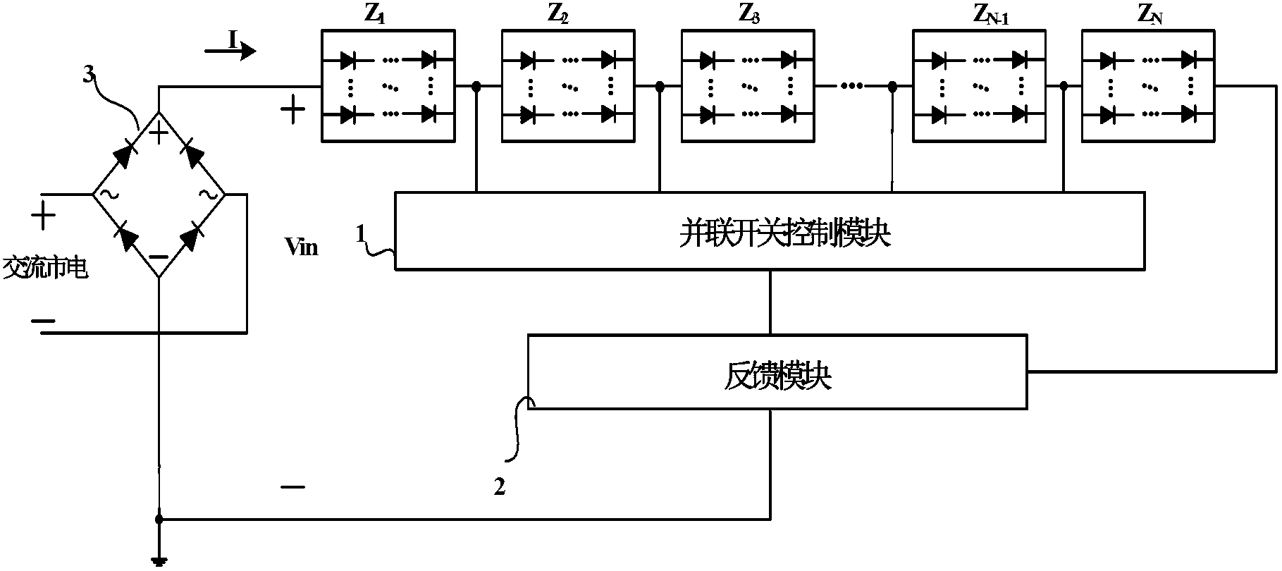
[0042] refer to Figure 4 , the LED drive circuit of the present invention includes a parallel high-voltage switch control module 1, a feedback module 2, a rectifier bridge 3 and N load networks Z 1 ~ Z N , N≥1.

[0043] The N load network Z 1 ~ Z N , a single group is connected in series between the rectifier bridge 3 and the feedback module 2, wherein each load network is composed of L strings of light-emitting diodes connected in parallel, and each string of light-emitting diodes is composed of M light-emitting diodes in series, 1≤ M×N<100, L≥1.

[0044] The parallel high-voltage switch control module 1 consists of N-1 high-voltage switch devices S 1 ~S N-1 constitute; these high-voltage switching devices S 1 ~S N-1 The output terminal b is connected, and connected to the feedback module 2 and the Nth load network Z N The common terminal of the first high-voltage switching device S 1 The input a of is connected to the first load network Z 1 with a second load net...

Embodiment 2

[0051] refer to Figure 5 , the LED drive circuit of the present invention includes a parallel high-voltage switch control module 1, a feedback module 2, a rectifier bridge 3 and N load networks Z 1 ~ Z N , N≥1.

[0052] The N load network Z 1 ~ Z N , a single group is connected in series between the rectifier bridge 3 and the feedback module 2, wherein each load network is composed of L strings of light-emitting diodes connected in parallel, and each string of light-emitting diodes is composed of M light-emitting diodes in series, 1≤ M×N<100, L≥1.

[0053] The parallel high-voltage switch control module 1 consists of N-1 high-voltage switch devices S 1 ~S N-1 constitute; these high-voltage switching devices S 1 ~S N-1 The output terminals b of are respectively connected to the first N-1 resistors R of the feedback module 2 1 ~R N-1 ; The first high-voltage switching device S 1 The input a of is connected to the first load network Z 1 with a second load network Z ...


PUM


Abstract

The invention discloses a light-emitting diode (LED) driving circuit based on parallel switch control and mainly solves the problem in the existing driving circuit of being incapable of achieving high efficiency and power factor with low cost. The LED driving circuit comprises a parallel connection switch control module (1), a feedback module (2), a rectifier bridge (3) and N load networks. The rectifier bridge (3) is used for conducting full wave rectification on alternating current mains supply. The N load networks are connected in series in single unit mode and connected between the rectifier bridge (3) and the feedback module (2) in crossing mode, and public ends of two adjacent load networks are both connected with the parallel connection switch control module (1). The feedback module (2) is used for sampling current value flowing through the load networks and outputting N-1 control signals to the parallel connection switch control module (1) so as to control on-off of high voltage switch devices in the parallel connection switch control module (1) and achieve the purpose of adjusting loads. Due to the fact that peripheral devices are fewer, the LED driving circuit can be integrated on a lamp panel with the LED load networks directly, the size and manufacture cost of an LED are effectively reduced, circuit working efficiency and power factor are improved, and the LED driving circuit can be used in an LED bulb and an LED lamp tube.

Description

technical field [0001] The invention belongs to the technical field of electronic circuits, and relates to an analog integrated circuit, in particular to an LED driving circuit based on parallel switch control. Background technique [0002] In lighting applications, light-emitting diodes (LEDs) are considered to be one of the most potential light sources at present because of their high luminous efficiency, long life, high brightness, energy saving, environmental protection and durability. In order to give full play to its advantages and be fully compatible with the previous generation of lighting products such as incandescent lamps and energy-saving lamps, it is necessary to equip an LED drive circuit with small size, long life, low cost, and directly powered by AC mains to maximize Give full play to the advantages of LED itself. At present, there are many kinds of LED drive circuits powered by AC mains, which can be mainly divided into the following two categories. [00...

Claims


Application Information

Patent Timeline
IPC IPC(8): H05B37/02
Inventor 来新泉刘从何惠森邵丽丽
Owner 深圳德信微电子有限公司
Features
  • R&D
  • Intellectual Property
  • Life Sciences
  • Materials
  • Tech Scout
  • Unparalleled Data Quality
  • Higher Quality Content
  • 60% Fewer Hallucinations
Learn More