Charged particle accelerator and charged particle acceleration method
A technology of charged particles and accelerators, applied in DC voltage accelerators, linear accelerators, magnetic resonance accelerators, etc., can solve the problems of cost increase, inability to increase energy gain, increase in the number of device components, etc., and achieve the effect of large energy gain
- Summary
- Abstract
- Description
- Claims
- Application Information
AI Technical Summary
Problems solved by technology
Method used
Image
Examples
Embodiment approach 1
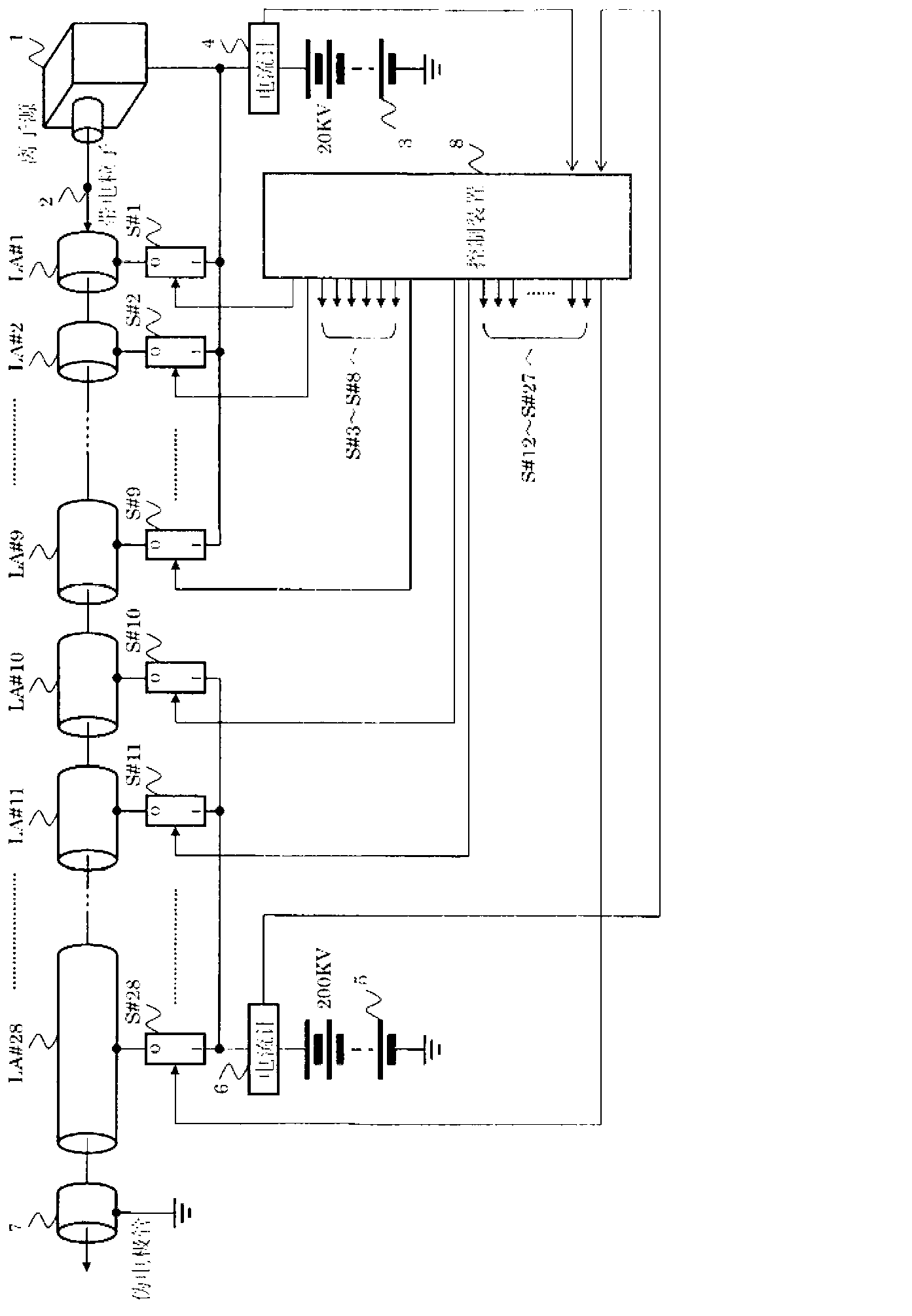
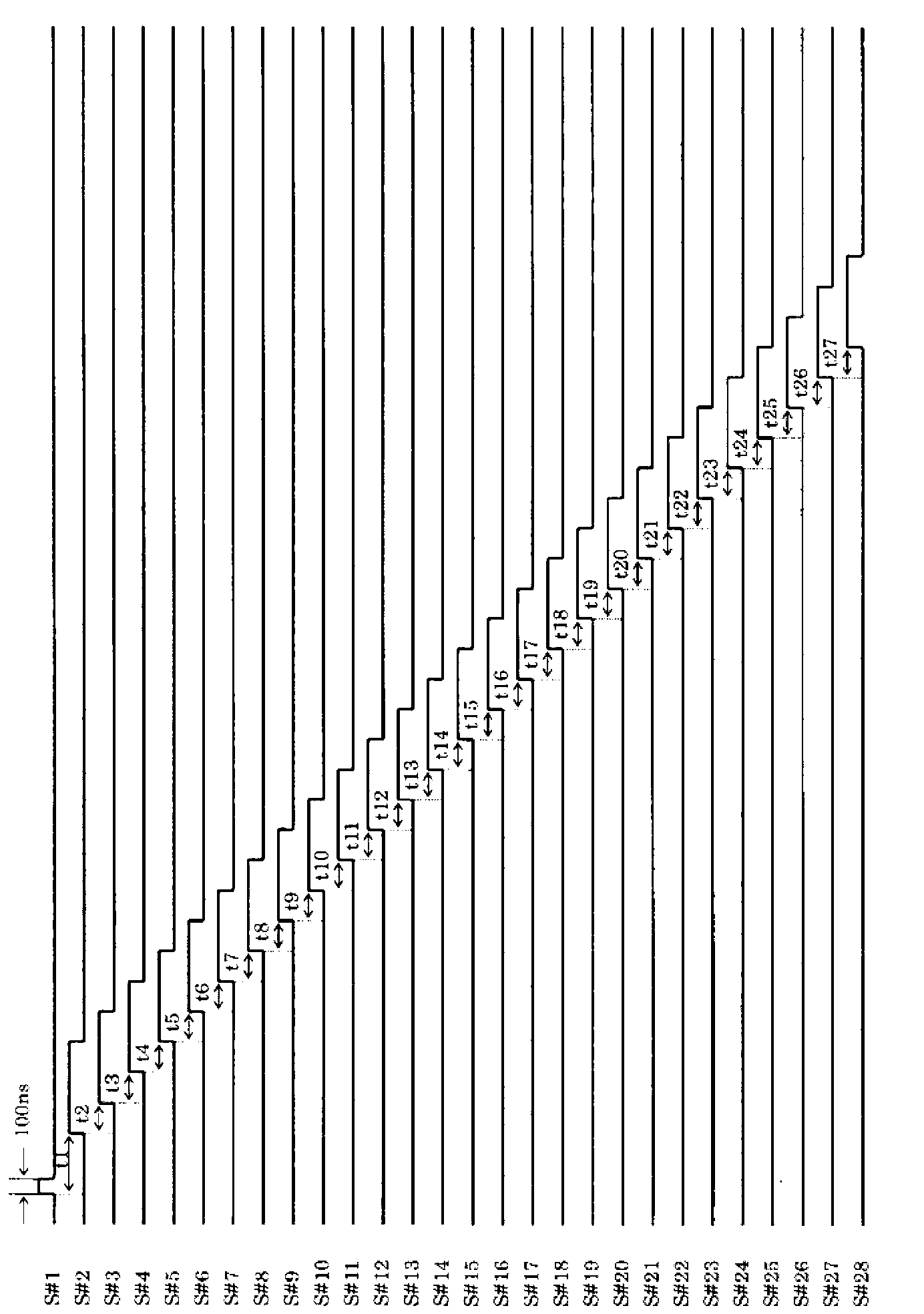
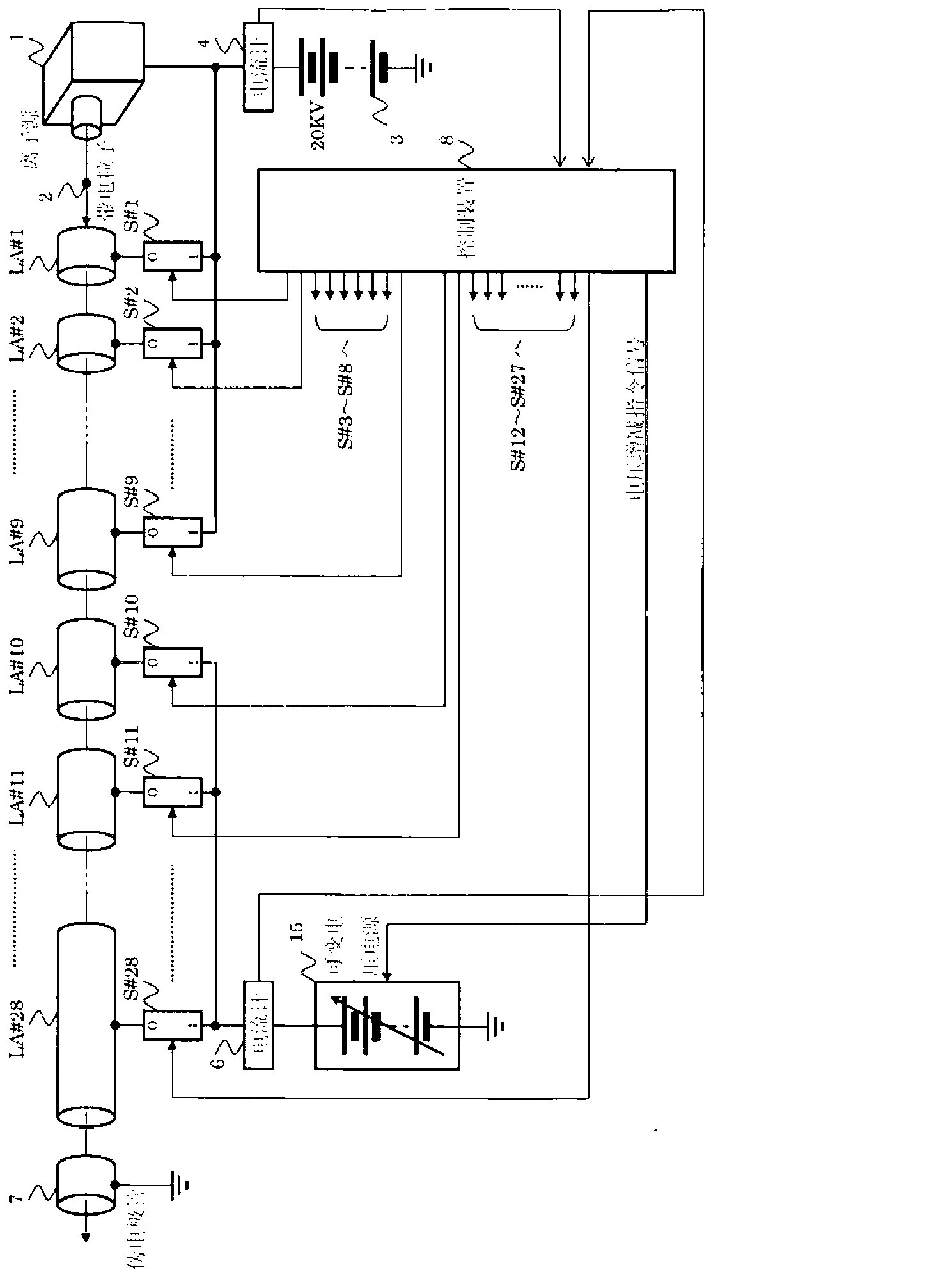
[0079] figure 1 It is a configuration diagram of a linear orbit type charged particle accelerator according to Embodiment 1 of the present invention. in figure 1 Among them, 1 is the ion source, 2 is the charged particles drawn from the ion source, and LA#1~LA#28 are 28 accelerating electrode tubes for accelerating the charged particles 2, including the final stage dummy electrode tube 7. Linear (straight line). 3 is a 20KV DC power supply, its output is connected to 9 switching circuits via ammeter 4 The I terminal. Similarly, 5 is a 200KV DC power supply, and its output is connected to 19 switching circuits via ammeter 6 The I terminal. 8 is the control device, connected to the output of the ammeters 4 and 6. Switching circuit The O terminals are respectively connected to the acceleration electrode tube The output of the control device 8 is connected to the switching circuit It is configured to be able to switch each switching circuit in accordance with an instructio...
Embodiment approach 2
[0106] Figure 4A and Figure 4B Each is a plan view and a side view showing the structure of a spiral orbit type charged particle accelerator according to Embodiment 2 of the present invention. in Figure 4A and Figure 4B Among them, 40 is a charged particle, 41 is an acceleration unit, 42 is an adjustment unit, 43 is a detection unit, and 44 and 45 are deflection magnets.
[0107] The detailed structures of the acceleration unit 41, the adjustment unit 42 and the detection unit 43 are shown in Figure 5A~Figure 5C , Figure 6A~Figure 6C and Figure 7A~Figure 7C . The acceleration unit 41 is an assembly of modules with a width of 60 mm, a height of 30 mm, and a depth of 30000 mm (30 m) called an acceleration unit. Similarly, the adjustment unit 42 is an assembly of modules with a width of 60 mm, a height of 30 mm, and a depth of 6050 mm called an adjustment unit, and the detection unit 43 is an assembly of modules with a width of 60 mm, a height of 30 mm, and a depth of 60 mm c...
Embodiment approach 3
[0143] Figure 21 It is a schematic diagram showing the configuration of a charged particle detection system according to Embodiment 3 of the present invention. in Figure 21 Among them, 40 is a charged particle, 50 is a detection electrode tube #1, 51 is a detection electrode tube #2, 52 is a detection electrode tube #3, 54 is a 1KV DC power supply, and 55 is an ammeter. For use Figure 4A and Figure 4B The spiral orbit type charged particle accelerator shown accelerates the charged particles (6-valent carbon ions), and it needs to be accelerated to 2MeVZu with the previous accelerator. in Figure 21 In the example shown, charged particles accelerated to 2 MeV are incident from the conveying path 56 into the primary acceleration unit AC#1 of the spiral orbit type charged particle accelerator.
[0144] Next, the operation of the charged particle detection system with the above-mentioned structure will be described. A fixed voltage is applied to the three detection electrode tub...
PUM
 Abstract
Description
Claims
Application Information
 - R&D
- Intellectual Property
- Life Sciences
- Materials
- Tech Scout
- Unparalleled Data Quality
- Higher Quality Content
- 60% Fewer Hallucinations
Browse by: Latest US Patents, China's latest patents, Technical Efficacy Thesaurus, Application Domain, Technology Topic, Popular Technical Reports.
© 2025 PatSnap. All rights reserved.Legal|Privacy policy|Modern Slavery Act Transparency Statement|Sitemap|About US| Contact US: help@patsnap.com


