High-speed metal wire drawing machine

A metal wire and wire drawing machine technology, applied in the field of high-speed metal wire wire drawing machines, can solve the problems of low wire drawing speed, inconvenient replacement, and high mold cost, and achieve the advantages of convenient replacement of synchronous pulleys, reduction of intermediate drive shafts, and reduction of mold costs. Effect

Active Publication Date: 2013-04-10
HANGZHOU XINGGUAN MACHINERY
View PDF11 Cites 13 Cited by
  • Summary
  • Abstract
  • Description
  • Claims
  • Application Information

AI Technical Summary

Problems solved by technology

However, the current aluminum wire drawing machine has the following common technical problems in the design of the transmission structure: 1) The transmission structure is complex, through multiple sets of gear transmission, the noise is large, the wire drawing speed is low, and the rotation of multiple shafts requires a certain amount of motor power. The effective power of the aluminum wire drawing machine is reduced, which causes unnecessary waste for the user; 2) The transmission stability of the gear transmission is poor after wear and tear, and the installation and maintenance requirements are high and the replacement is inconvenient; 3) The fixed speed wheel and the high-speed tower The wheel set is connected by chain (or gear) transmission, the speed ratio relationship between the two is fixed, and the speed ratio between the traction constant speed theory and the high-speed tower wheel cannot be adjusted. This design makes the drawing mold must: A set of molds is required for one outlet specification, and multiple sets of molds are required for multiple specifications, and the cost of molds is high.

Method used


Image

  • High-speed metal wire drawing machine

Examples


Embodiment Construction

[0018] Below in conjunction with accompanying drawing, the present invention will be further described:

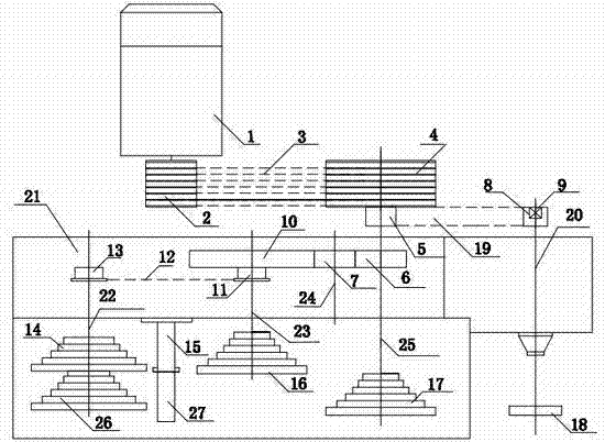
[0019] Such as figure 1 As shown, a high-speed metal wire drawing machine includes a frame 21 and a motor 1. On the frame 21, a low-speed guide wheel set 14, a low-speed mold frame 15, a low-speed tower wheel set 16, and a high-speed guide wheel set 26 are sequentially arranged. , high-speed mold frame 27, high-speed tower wheel group 17 and fixed speed wheel 18, on the described low-speed mold frame 15, low-speed mold groups are arranged, and the number of molds set on the low-speed mold group is the same as the number of tower wheels on the low-speed tower wheel group 16. Number is the same; Die group is arranged on the formwork 26, and the number of molds provided on the die group is identical with the number of tower wheels on the high-speed tower wheel group 17. The motor 1 is connected with the driving pulley 2, the driving pulley 2 is connected with the driven pull...


PUM


Abstract

The invention relates to a high-speed metal wire drawing machine, and belongs to the technical field of a metal wire drawing machine. The high-speed metal wire drawing machine comprises a rack and a motor, wherein a low-speed guide wheel set, a low-speed mould base, a high-speed guide wheel set, a high-speed mould base and the like are arranged on the rack; the motor is sequentially connected with a driving pulley, a driven pulley and a high-speed cone pulley set; the high-speed cone pulley set is in transmitted connection with a constant-speed wheel and is in meshed and transmitted connection with a low-speed cone pulley set; the low-speed guide wheel set is connected with the low-speed cone pulley set. The chain or gear transmission of the constant-speed wheel and the high-speed cone pulley set is changed into synchronous belt transmission, synchronous belt wheels are connected with shafts through taper locks, the replacement is convenient, and therefore the different speed ratios between the constant-speed wheel and the high-speed cone pulley set is obtained, so that only one mould is needed when customers draw a variety of specifications of metal wires. The mould cost is greatly reduced. The high-speed metal wire drawing machine has the advantages of simple design, high wire drawing speed, low energy consumption, good economic benefit and strong practicality, greatly reduces transmission noises, and brings security assurance to the personal safety of operating personnel.

Description

technical field [0001] The invention belongs to the technical field of high-speed metal wire drawing machines, and in particular relates to a high-speed metal wire drawing machine with simple structure, low transmission noise, high efficiency, low energy consumption and strong practical applicability. Background technique [0002] At present, the transmission device of the metal wire drawing machine commonly used in production is usually driven by a power source motor through gear transmission to rotate multiple tower shafts and transition shafts, and power transmission is performed between each tower shaft through gears. However, the current aluminum wire drawing machine has the following common technical problems in the design of the transmission structure: 1) The transmission structure is complex, through multiple sets of gear transmission, the noise is large, the wire drawing speed is low, and the rotation of multiple shafts requires a certain amount of motor power. T...

Claims


Application Information

Patent Timeline
Patent Type & Authority Applications(China)
IPC IPC(8): B21C1/12
Inventor 袁关兴
Owner HANGZHOU XINGGUAN MACHINERY
Why Eureka
Try Eureka