Manufacturing method for hot stamping die cooling pipeline

A technology for hot stamping dies and cooling pipes is applied in the field of manufacturing cooling pipes inside hot stamping dies, and can solve the problems of melt-through of embedded metal pipes, easy water leakage, uneven cooling, etc.

Inactive Publication Date: 2013-04-10
ADVANCED MFG TECH CENT CHINA ACAD OF MASCH SCI & TECH
View PDF9 Cites 3 Cited by
  • Summary
  • Abstract
  • Description
  • Claims
  • Application Information

AI Technical Summary

Problems solved by technology

[0005] The purpose of this invention is to provide a novel manufacturing method for hot stamping die cooling pipes, which can solve the problems of drilled cooling pipes not conforming to the shape, uneven cooling, and leakage, and also solve the melt-through of pre...

Method used


Image

  • Manufacturing method for hot stamping die cooling pipeline
  • Manufacturing method for hot stamping die cooling pipeline

Examples


Embodiment Construction

[0013] The specific embodiment of the invention will be further described below in conjunction with the accompanying drawings.

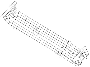
[0014] According to hot stamping parts, designs such as figure 1 The hot stamping die cooling system shown, the cooling system is completely conformal. figure 1 The cooling pipe shown is made of silicon-based ceramic material, and after the support core (1) and the main core (2) are manufactured, they are bonded into a whole with a silicon-based adhesive.

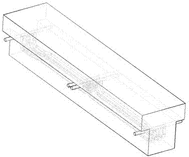
[0015] According to the shape of the part, design the corresponding sand mold shape of the mold, and leave a fixing hole for the ceramic core cooling pipe. Fix the ceramic core cooling pipe in the sand mold before casting, such as figure 2 As shown, the low-temperature pouring method is adopted in the bottom injection casting method. The starting temperature of molten steel is controlled at 10-30°C above the melting point of molten steel, and the temperature at the end of casting is 5°C highe...


PUM


Abstract

The invention relates to a manufacturing method for a hot stamping die cooling pipeline, which is used for forming an integrated cooling pipeline in the process of casting the hot stamping die. The core of the method is that the hot stamping die cooling pipeline is manufactured by embedding a ceramic core, casting to form an integrated hot stamping die and cleaning the ceramic core by an alkali detonation process to form the die cooling pipeline, wherein design of the ceramic core and cleaning of the ceramic core are related. The cooling pipeline can be accurately positioned in the hot stamping die by the method provided by the invention and the internal quality of the cooling pipeline is improved, so that the cooling effect of the cooling pipeline is improved, the defects that a drilling type cooling pipeline cannot be random, is cooled non-uniformly and is leaked, and the pipeline is melted through and collapsed when the embedded metal cooling pipeline is cast are overcome, and the hot pressing die with high quality and the complex pipeline can be produced.

Description

technical field [0001] The invention belongs to the field of hot stamping die manufacturing, and mainly relates to a manufacturing method of a cooling pipeline inside the hot stamping die. Background technique [0002] Hot stamping dies need to have cooling channels inside. The more complex the mold surface is, the more difficult it is to process the internal channels. Currently, there are two common methods to obtain mold cooling channels. One is: the mold is manufactured in blocks, and the cooling pipe is obtained by drilling; the other is: the metal pipe is pre-embedded and then cast to obtain the cooling pipe. [0003] The method of manufacturing the mold in blocks to obtain the cooling pipe is: divide the whole mold into several blocks, drill and process the cooling pipes on each block, and then connect the blocks together to form the cooling pipe of the mold . The disadvantages of this method are: the pipes in each block are straight pipes, and the cooling pipes cann...

Claims


Application Information

Patent Timeline
IPC IPC(8): B22C9/02B22C9/24
Inventor 单忠德张密兰许应蔡万华姜超叶永盛庄百亮
Owner ADVANCED MFG TECH CENT CHINA ACAD OF MASCH SCI & TECH
Why Eureka
Try Eureka