
Liquid reservoir air inlet and outlet pipe and manufacturing method as well as application thereof

A technology for the inlet pipe and air inlet and outlet pipes of the liquid accumulator, which is applied in the field of compressors and can solve the problems of low electrical efficiency, short service life, and poor quality

Active Publication Date: 2013-04-10
DONGGUAN JINRUI HARDWARE PROD
View PDF1 Cites 11 Cited by
  • Summary
  • Abstract
  • Description
  • Claims
  • Application Information

AI Technical Summary

Problems solved by technology

[0002] At present, most of the air inlet and outlet pipes of the existing compressor liquid accumulator are whole copper pipes, which are usually connected with the shell of the liquid accumulator by flame brazing or high frequency brazing with silver solder. The silver solder is not only expensive, but also In the production process, a large amount of carbon dioxide is generated to pollute the environment, and the extensive use of copper pipes further increases the production cost
In addition, flame brazing must adopt methods such as lap joints and sleeve inlays to increase the area of ​​the joint connection surface to make up for the lack of brazing strength, and it will also produce a large amount of carbon dioxide due to the use of solder, which will pollute the environment At the same time, the cost of the above-mentioned compressor exhaust pipe is increased due to the use of a large amount of copper
High-frequency brazing has low electrical efficiency, high working voltage, poor safety, high brittleness, easy cracking, and short service life. Moreover, when the air conditioner manufacturer re-welds, it is easy to cause secondary melting of the solder, making the quality lower. Poor, not easy to weld the exhaust pipe in the compressor field

Method used


Image

  • Liquid reservoir air inlet and outlet pipe and manufacturing method as well as application thereof
  • Liquid reservoir air inlet and outlet pipe and manufacturing method as well as application thereof
  • Liquid reservoir air inlet and outlet pipe and manufacturing method as well as application thereof

Examples


Embodiment Construction

[0030] The present invention is further described in conjunction with the following examples.

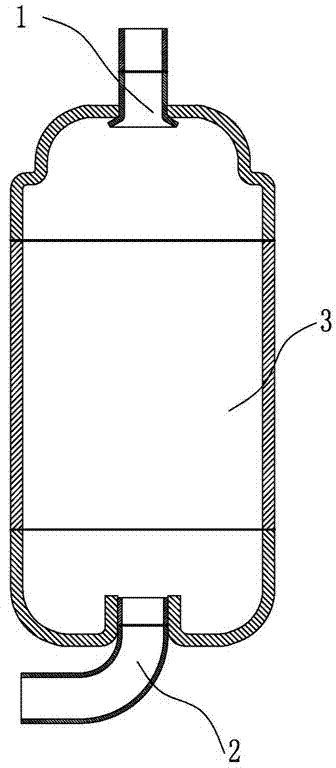
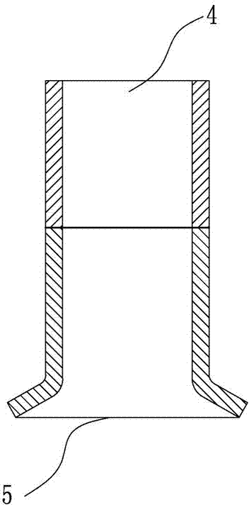
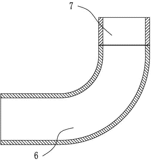
[0031] A liquid reservoir inlet and outlet pipe, such as figure 1 , figure 2 and image 3 As shown, it includes an air inlet pipe 1 and an air outlet pipe 2 , the air inlet pipe 1 is arranged on the upper part of the liquid reservoir 3 , and the air outlet pipe 2 is arranged on the lower part of the liquid reservoir 3 . The intake pipe 1 comprises a first intake pipe 4 and a second intake pipe 5, in the butt end of the first intake pipe 4 and the butt end of the second intake pipe 5, the inner diameter of one of the butt ends is smaller than the outer diameter of the other end, and the two or non-socketed. The first air inlet pipe 5 is a copper pipe or a copper-plated pipe, and the second air inlet pipe 5 is any one of an iron pipe, a copper-plated pipe and a copper pipe. Preferably, the second air inlet pipe 5 is an iron pipe; the air outlet pipe 2 includes The first air outle...


PUM


Abstract

The invention relates to the field of a compressor, in particular to a liquid reservoir air inlet and outlet pipe and application thereof. The liquid reservoir air inlet and outlet pipe comprises an air inlet pipe and an air outlet pipe, wherein the air inlet pipe is arranged on the upper part of a liquid reservoir; the air outlet pipe is arranged on the lower part of the liquid reservoir; the air inlet pipe comprises a first air inlet pipe and a second air inlet pipe; the first air inlet pipe and the second air inlet pipe are butt-welded through flash welding; the air outlet pipe comprises a first air outlet pipe and a second air outlet pipe; and the first air outlet pipe and the second air outlet pipe are butt-welded through flash welding. By using the liquid reservoir air inlet and outlet pipe of the structure, the using amount of copper is saved, and the manufacturing cost is reduced; and the second air inlet pipe and the second air outlet pipe are all connected to a housing of the liquid reservoir through the electric resistance welding free of solder. The technology of the invention is simple, the solder is saved, further the manufacture cost is reduced, meanwhile in the manufacture process exhaust gas such as carbon dioxide or the like is not generated to pollute the environment.

Description

technical field [0001] The invention relates to the field of compressors, in particular to a gas inlet and outlet pipe of a liquid accumulator, a manufacturing method and application thereof. Background technique [0002] At present, most of the air inlet and outlet pipes of the existing compressor liquid accumulator are whole copper pipes, which are usually connected with the shell of the liquid accumulator by flame brazing or high frequency brazing with silver solder. The silver solder is not only expensive, but also In the production process, a large amount of carbon dioxide is produced to pollute the environment, and the extensive use of copper pipes further increases the production cost. In addition, flame brazing must adopt methods such as lap joints and sleeve inlays to increase the area of ​​the joint connection surface to make up for the lack of brazing strength, and it will also produce a large amount of carbon dioxide due to the use of solder, which will pollute t...

Claims


Application Information

Patent Timeline
IPC IPC(8): F25B43/00B23K11/04
Inventor 陈金龙
Owner DONGGUAN JINRUI HARDWARE PROD
Learn More