

Multichannel nuclear magnetic resonance underground water detecting instrument and field work method thereof
A nuclear magnetic resonance and detector technology, which is used in electronic magnetic resonance/nuclear magnetic resonance detection, water resource assessment, climate sustainability, etc. problems, to achieve the effect of improving anti-jamming capability, improving lateral resolution and accuracy, and reducing risks
- Summary
- Abstract
- Description
- Claims
- Application Information
AI Technical Summary
Problems solved by technology
Method used
Image

Examples
Embodiment 1
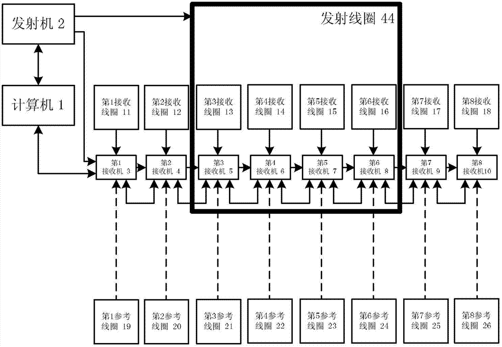
[0038] The computer 1 is connected with the transmitter 2 through the transmitter communication interface 27, the computer 1 is connected with the receiver input communication interface 38 of the first receiver 3 through the receiver input communication interface 38, and the first receiver 3 is connected with the receiver output communication interface 37 Connect with the receiver input communication interface 38 of the 2nd receiver 4, the 2nd receiver 4 is connected with the receiver input communication interface 38 of the 3rd receiver 5 through the receiver output communication interface 37, the 3rd receiver 5 passes the receiver The output communication interface 37 is connected with the receiver input communication interface 38 of the 4th receiver 6, the 4th receiver 6 is connected with the receiver input communication interface 38 of the 5th receiver 7 through the receiver output communication interface 37, the 5th receiver 7 is connected with the receiver input communicat...
Embodiment 2
[0046] The computer 1 is connected with the transmitter 2 through the transmitter communication interface 27, the computer 1 is connected with the receiver input communication interface 38 of the first receiver 3 through the receiver input communication interface 38, and the first receiver 3 is connected with the receiver output communication interface 37 Connect with the receiver input communication interface 38 of the 2nd receiver 4, the 2nd receiver 4 is connected with the receiver input communication interface 38 of the 3rd receiver 5 through the receiver output communication interface 37, the 3rd receiver 5 passes the receiver The output communication interface 37 is connected with the receiver input communication interface 38 of the 4th receiver 6, the 4th receiver 6 is connected with the receiver input communication interface 38 of the 5th receiver 7 through the receiver output communication interface 37, the 5th receiver 7 is connected with the receiver input communicat...
Embodiment 3
[0054] The computer 1 is connected with the transmitter 2 through the transmitter communication interface 27, the computer 1 is connected with the receiver input communication interface 38 of the first receiver 3 through the receiver input communication interface 38, and the first receiver 3 is connected with the receiver output communication interface 37 Connect with the receiver input communication interface 38 of the 2nd receiver 4, the 2nd receiver 4 is connected with the receiver input communication interface 38 of the 3rd receiver 5 through the receiver output communication interface 37, the 3rd receiver 5 passes the receiver The output communication interface 37 is connected with the receiver input communication interface 38 of the 4th receiver 6, the 4th receiver 6 is connected with the receiver input communication interface 38 of the 5th receiver 7 through the receiver output communication interface 37, the 5th receiver 7 is connected with the receiver input communicat...
PUM
 Abstract
Description
Claims
Application Information