
Electric reactor with integrally-bound iron core and binding method of iron core of electric reactor

A reactor and iron core technology, applied in transformer/inductor magnetic cores, circuits, electrical components, etc., can solve the problems of long production cycle, high labor intensity of workers, long binding time, etc., to reduce the temperature rise of the iron core, improve Labor conditions, the effect of shortening the manufacturing cycle

Inactive Publication Date: 2013-04-10
QINGDAO HAIWO ELECTRICAL EQUIP
View PDF5 Cites 2 Cited by
  • Summary
  • Abstract
  • Description
  • Claims
  • Application Information

AI Technical Summary

Problems solved by technology

[0003] (1) The thickness of the binding is generally 1.5mm or 2mm, and the thickness of the adhesive tape is 0.1mm. Each binding requires 15 or 20 layers. The binding time is long and the production efficiency is low;
[0004] (2) The labor intensity of the workers is high and the operating conditions are not good;
[0005] (3) The adhesive tape needs to be cured, and the production cycle is long;
[0006] (4) The cost of binding glass adhesive tape is high and the waste is large;
The efficiency of manual binding is low, the appearance quality is poor, and the binding force is small. When binding with an iron core binding machine, the production cost of the binding machine and the iron core fixture is high, and the process operation is complicated.

Method used


Image

  • Electric reactor with integrally-bound iron core and binding method of iron core of electric reactor

Examples


Embodiment Construction

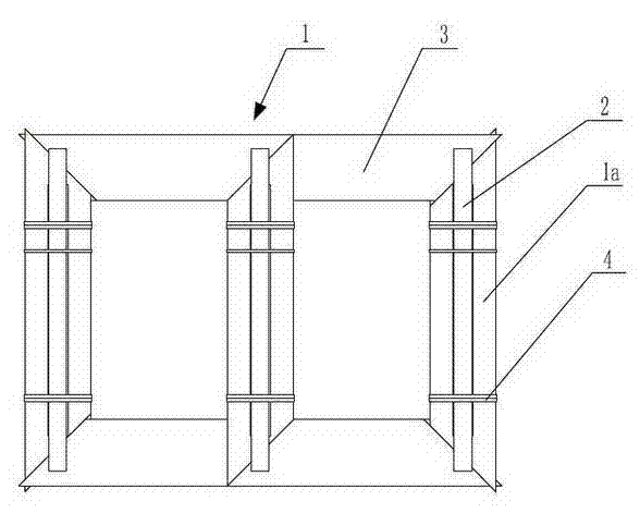
[0030] Such as figure 1 As shown, in the reactor of the present invention whose iron core is bound as a whole, the three-column iron core 1 is formed by stacking silicon steel sheets 3, and adjustment pads 2 are arranged along the outer surfaces of both sides of the iron core post 1a, outside the adjustment pads 2 There is a binding strap 4 that binds the iron core column 1a and the adjustment pad 2 together. The binding strap 4 is made of Tenax polyester tape, and the binding strap 4 is tied to both ends of the adjustment pad 2. Turn binding strap 4, the other end is bound two turns of binding strap 4, and the spacing of binding strap is 120-150mm.

[0031] The binding method of the reactor iron core comprises the following steps: forming a three-column iron core 1 by stacking silicon steel sheets, and setting adjustment pads 2 along the outer surfaces of both sides of the iron core post 1a; The column 1a and the adjustment pad 2 are bound together with Tenax polyester bindi...


PUM

PropertyMeasurementUnit
Spacingaaaaaaaaaa

Abstract

The invention relates to an electric reactor with an integrally-bound iron core and a binding method of an iron core of the electric reactor. The electric reactor comprises a three-column type iron core which is formed by stacking silicon steel sheets, adjusting pad strips are arranged along two side outer surfaces of an iron core column, and binding tapes which are used for integrally binding the iron core column and the adjusting pad strips are arranged outside the adjusting pad strips. The binding method of the iron core of the electric reactor comprises the following steps of firstly, forming the three-column type iron core by stacking the silicon steel sheets, and arranging the adjusting pad strips on the two outer side surfaces of the iron core; and then, integrally binding the iron core column and the adjusting pad strips at the outer sides of the adjusting pad strips. By adopting the structure and the binding method, disclosed by the invention, the binding tapes not only has the stretching resistance like a steel tape, but also has the shock-proof extensibility, solidification is not needed, a large amount of working hours can be saved, the manufacturing period of the iron core is shortened, the production efficiency is increased, the labor intensity of a worker is low, the running noise of a transformer is reduced, the temperature rising of the iron core is effectively reduced, and the binding arrangement of polyester tapes is regular and attractive.

Description

technical field [0001] The invention relates to the technical field of reactors, in particular to a reactor with an integrally bound iron core, and a method for binding the iron core of the reactor. Background technique [0002] Reactors, especially magnetic valve controllable reactors, due to the air gap structure of small iron cores, the silicon steel sheets are small in shape, the iron core has many seams, and the binding effect is not ideal, resulting in excessive noise, which easily exceeds the national standard . At present, most transformer manufacturers use alkali-free glass fiber tape plus epoxy paint or latitude-free glass adhesive tape to tighten and wind the iron core. After binding, it needs to be cured for a period of time. The disadvantage of this process is: [0003] (1) The thickness of the binding is generally 1.5mm or 2mm, and the thickness of the adhesive tape is 0.1mm. Each binding requires 15 or 20 layers. The binding time is long and the productio...

Claims


Application Information

Patent Timeline
IPC IPC(8): H01F27/26H01F27/245H01F41/02
Inventor 张式雷王光辉
Owner QINGDAO HAIWO ELECTRICAL EQUIP
Learn More