Magnetic resonant coupling wireless energy transmission system based on filter design principles

A technology of wireless energy transmission and magnetic resonance coupling, which is applied in the direction of electromagnetic wave systems, electrical components, circuit devices, etc., can solve the problems of large system occupation, low transmission power and low transmission efficiency, and achieve high transmission power and transmission efficiency. Effect of Transmission Frequency Drift

Inactive Publication Date: 2013-04-10
TSINGHUA UNIV
View PDF4 Cites 11 Cited by
  • Summary
  • Abstract
  • Description
  • Claims
  • Application Information

AI Technical Summary

Problems solved by technology

[0005] The purpose of the present invention is to propose a magnetic resonance coupling wireless energy transmission system based on filter design principles in view of the problems of low transmission power and transmission efficiency and large system occupation space in the existing magnetic resonance coupling wireless energy transmission technology

Method used


Image

  • Magnetic resonant coupling wireless energy transmission system based on filter design principles
  • Magnetic resonant coupling wireless energy transmission system based on filter design principles
  • Magnetic resonant coupling wireless energy transmission system based on filter design principles

Examples


Embodiment 1

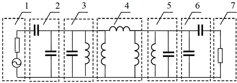
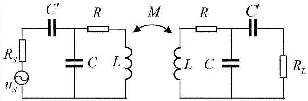
[0025] The flattest low-pass filter prototype is taken as an example to illustrate the process of realizing magnetic resonance coupling wireless energy transmission. The g of this filter is obtained by looking up the table 0 =1, g 1 =g 2 =1.414. Take the 3dB relative bandwidth as 0.05, the working frequency as 10MHz, G 0 =0.02S, design variable C 0 =20pF, calculated figure 2 The component values ​​in are C'=28pF, C=24pF, L=4899nH, M=167nH. These capacitors are respectively implemented by very small monolithic capacitors. The inductance is realized by winding a copper wire with a cross-sectional radius of 1mm into a flat circular coil with a radius of 20cm. The loss resistance is about R=0.5Ω. If the two coils Coaxially placed, and the distance between them is 42cm, the required mutual inductance can be realized, thereby completing the magnetic resonance coupling wireless energy transmission system. The power and efficiency of this transmission system obtained by circui...

Embodiment 2

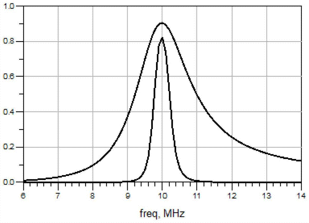
[0027] From the simulation results of Example 1 image 3 It can be seen that if the relative bandwidth of the filter is set to 0.05, the passband of energy transmission at the operating frequency of 10MHz is narrow, so the optimal transmission frequency may drift due to systematic errors and the transmission power and transmission efficiency will decrease. To solve this problem, the relative bandwidth can be set larger. If the 3dB relative bandwidth is set to 0.1, and other parameters remain unchanged, the calculated figure 2The component values ​​in are respectively C'=33.7pF, C=20pF, L=4752nH, M=313nH. These capacitors are realized by very small monolithic capacitors. The inductance can be realized by fine-tuning the coil on the basis of the above-mentioned embodiment 1. The required mutual inductance can be realized by placing the coaxial distance between the two coils at 35cm. A magnetic resonance coupled wireless energy transfer system is realized. Figure 4 is the si...


PUM


Abstract

The invention discloses a magnetic resonant coupling wireless energy transmission system based on filter design principles in the technical field of design of wireless energy transmission systems; and the magnetic resonant coupling wireless energy transmission system is instructed and designed by applying design principles of an inductive coupling second-order band-pass filter. The system comprises a power supply, an admittance converter, a parallel resonant circuit and a load. The design method uses synthetic design method principles of a filter to effectively terminate the relationship between the transmission power, the transmission efficiency, the transmission distance and the working frequency in the wireless energy transmission system and the values of all electronic elements in a circuit system, and the designed transmission system can work in the state of highest transmission power and transmission efficiency; and at the same time, through designing a certain band width, the wireless energy transmission system is used in a wider frequency range, so that the problem of reduced transmission power and transmission efficiency due to optimal transmission frequency variations caused by system errors is solved better.

Description

technical field [0001] The invention belongs to the technical field of wireless energy transmission system design, and in particular designs a magnetic resonance coupling wireless energy transmission system based on filter design principles. Background technique [0002] Magnetic resonance coupling wireless energy transfer technology is a new type of wireless energy transfer technology, which has great advantages over traditional magnetic coupling wireless energy transfer technology. Magnetic resonance coupling wireless energy transmission technology can achieve high transmission power and transmission efficiency at a long distance, realize wireless transmission in the true sense, and overcome the traditional magnetic coupling wireless energy transmission technology that can only be achieved at a very short distance Disadvantages of use. [0003] However, as a new type of energy transmission technology, the magnetic resonance coupling wireless energy transmission technology...

Claims


Application Information

Patent Timeline
Patent Type & Authority Applications(China)
IPC IPC(8): H02J17/00H02J50/12
Inventor 周济郭云胜李勃
Owner TSINGHUA UNIV
Why Eureka
Try Eureka