Control device and control method for injection molding machine

A technology for an injection molding machine and a control device, which is applied to the control device and the control field of the injection molding machine, can solve the problems of burr and mold release, the size of the molded product is too large, and the pressure response is oscillated, and the effect of stable pressure control is achieved.

Active Publication Date: 2013-04-10
MITSUBISHI ELECTRIC CORP
View PDF6 Cites 7 Cited by
  • Summary
  • Abstract
  • Description
  • Claims
  • Application Information

AI Technical Summary

Problems solved by technology

[0004] During the holding operation, if the pressure response overshoots or oscillates, a higher pressure than the desired pressure is applied, and as a result, the size of the molded product may become too large, or Burrs or poor mold release
In addition, in the worst case, it is possible to make the pressure response continuously oscillate, causing the control system to be unstable
[0005] There is a problem that it is necessary to manually adjust the pressure control through trial and error while confirming the pressure response in order to ensure a certain degree of followability to the pressure command value without overshooting or oscillation in the pressure response. control parameters, the time required for adjustment increases
[0006] In addition, there is also a problem that appropriate control parameters differ depending on the shape of the mold and the type of resin, and it is necessary to adjust the appropriate control parameters according to the shape of the mold and the type of resin.

Method used


Image

  • Control device and control method for injection molding machine
  • Control device and control method for injection molding machine
  • Control device and control method for injection molding machine

Examples


Embodiment approach 1

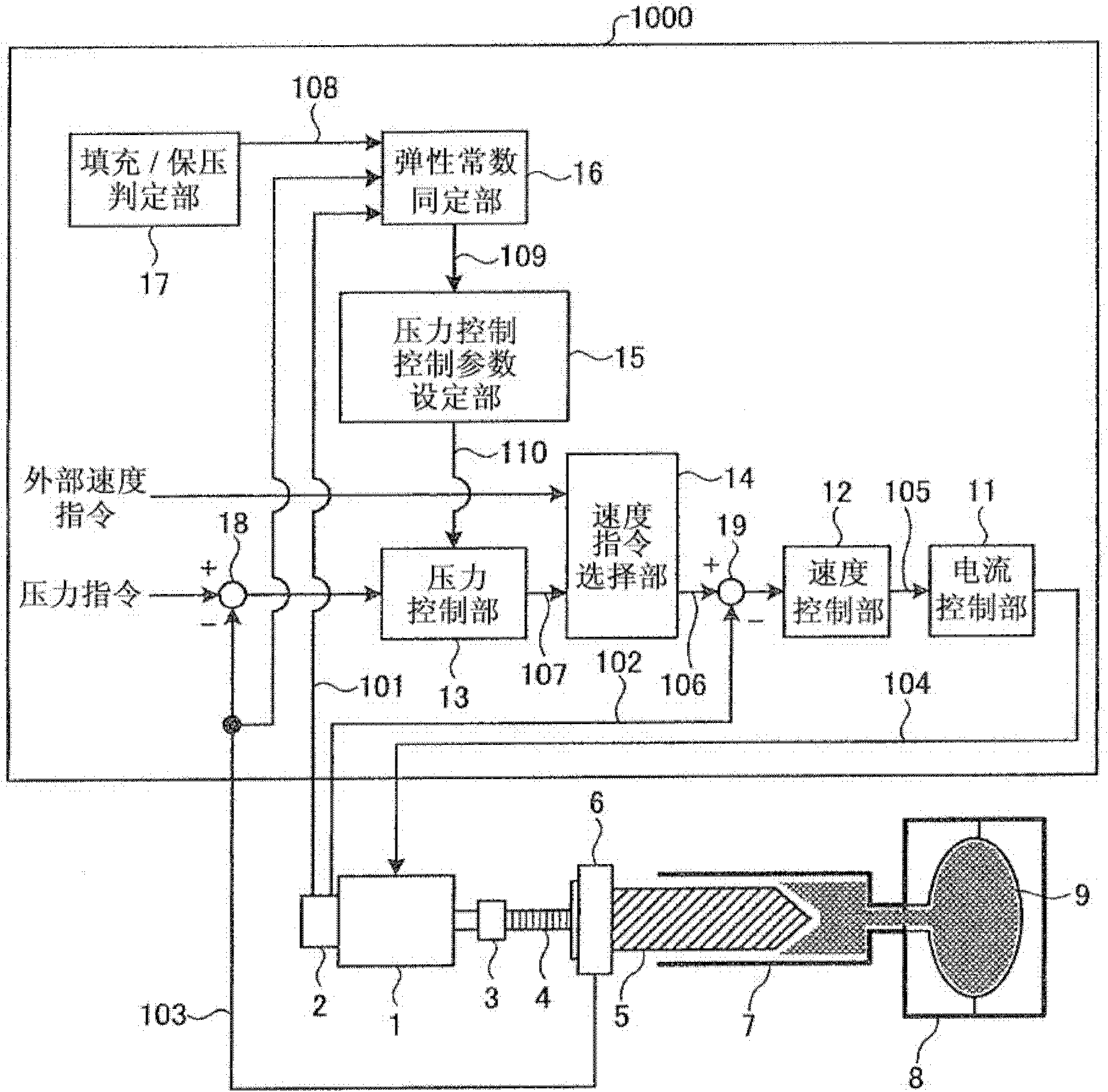
[0053] figure 1 It is a figure which shows the structure of the injection molding machine provided with the control apparatus concerning Embodiment 1 of this invention. As shown in the figure, the injection molding machine has a control device 1000 , a motor 1 , an encoder 2 , a coupling 3 , a ball screw 4 , a screw 5 , a load cell 6 , a cylindrical portion 7 , and a mold 8 .

[0054] The motor 1 is driven by current supplied from the control device 1000 . The encoder 2 detects the position and speed of the motor 1 and outputs the detection results as a position detection value 101 and a speed detection value 102 . The coupling 3 connects the rotating shaft of the motor 1 and the ball screw 4 . A screw 5 is connected to the ball screw 4 via a load cell 6 , and the screw 5 is used to fill and pressurize the mold 8 with the resin 9 filled in the cylindrical portion 7 . The load cell 6 detects the pressure when the screw 5 extrudes the resin 9 , and outputs the detection resul...

Embodiment approach 2

[0124] In Embodiment 1, the pressure and the position are recorded in step ST4, and the elastic constant K is determined based on the proportional relationship between the position of the motor 1 and the pressure established during the execution of the pressure-holding operation in step ST7. Instead of the position of the motor 1 , motor information other than the position, such as the speed of the motor 1 or the acceleration of the motor 1 , may be used.

[0125] The control device of Embodiment 2 uses the speed of the motor 1 instead of the position of the motor 1 . In addition, the control device of the second embodiment has the same components as those of the first embodiment except for the elastic constant constant unit. here, as Figure 5 As shown, the reference numeral 2000 is assigned to the control device of the second embodiment, and the reference numeral 21 is assigned to the elastic constant constant part of the second embodiment to distinguish them from the first...

Embodiment approach 3

[0145] In Embodiments 1 and 2, the test operation is performed in a continuous period from when the pressure-holding operation judging unit determines that the pressure-holding operation is being performed to when it determines that the pressure-holding operation is not being performed. Control parameters are obtained from the position and pressure data, and the control parameters are set in the pressure control unit after the pressure holding operation is completed (that is, after the above-mentioned continuous period ends). On the other hand, according to the control method of Embodiment 3, the elastic constant K is determined successively during the continuous period in which it is determined that the pressure maintaining operation is being performed and the filling / pressure maintaining determination unit 17 is determining that the pressure maintaining operation is being performed. Based on this information, the control parameters of the pressure control are updated at any t...


PUM


Abstract

In order to perform stable pressure control, provided is a control device for an injection molding machine which comprises: a filling/pressure keeping assessment unit which assesses whether or not the injection molding machine is performing a pressure keeping operation (Step ST3); an elastic constant identification unit which, when the filling/pressure keeping assessment unit assesses that the pressure keeping operation is performed (Yes in Step ST3), acquires a pressure detection value and a position detection value as motor operation information (Step ST4), and identifies an elastic constant K on the basis of the acquired pressure detection value and position detection value (Step ST7); and a pressure control parameter setting unit which calculates a proportional gain Ka of a pressure control unit so that a product of the proportional gain Ka of the pressure control unit and the elastic constant K is smaller than a velocity control band Omegasc of a velocity control unit (Step ST8), and sets the pressure control unit to the calculated proportional gain Ka(Step ST9).

Description

technical field [0001] The invention relates to a control device and a control method for controlling an injection molding machine. Background technique [0002] Conventionally, there is an injection molding machine in which a screw is driven by a motor, and a molten resin is filled and maintained in a mold by the operation of the screw to obtain a plastic molded product. The injection molding machine has a pressure sensor such as a load cell on the screw. Based on the control cycle using the pressure detection value of the pressure sensor, the pressure of the resin is controlled so that the pressure of the resin follows the pressure command applied from the outside. value. [0003] Here, in the pressure control described above, it is necessary to set control parameters such as gain to appropriate values. In particular, in the pressure-holding operation, when the control parameter is larger than an appropriate value, there is a problem that the pressure response (time resp...

Claims


Application Information

Patent Timeline
Patent Type & Authority Applications(China)
IPC IPC(8): B29C45/77B29C45/50
CPCB29C45/76B29C45/77B29C2945/76006B29C2945/76257B29C2945/76381B29C2945/76598B29C2945/76859B29C2945/76936B29C2945/76933
Inventor 上田浩一郎长谷川澄尾木英优小林幸彦
Owner MITSUBISHI ELECTRIC CORP
Why Eureka
Try Eureka