Micro-bubble generation device

A micro-bubble generation and micro-bubble technology, which is applied in water aeration, sustainable biological treatment, mixers, etc., can solve the problems of less bubbles and increased energy consumption of water supply pumps, and achieve good processing and assembly process, and easy operation Simple and convenient, low energy consumption effect

Inactive Publication Date: 2013-04-17
曾永芳
View PDF2 Cites 17 Cited by
  • Summary
  • Abstract
  • Description
  • Claims
  • Application Information

AI Technical Summary

Problems solved by technology

However, a large number of micro-bubble generating devices need to supply higher water pressure, thereby increasing the energy consumption of the water supply pump;...

Method used


Image

  • Micro-bubble generation device
  • Micro-bubble generation device
  • Micro-bubble generation device

Examples


Embodiment 1

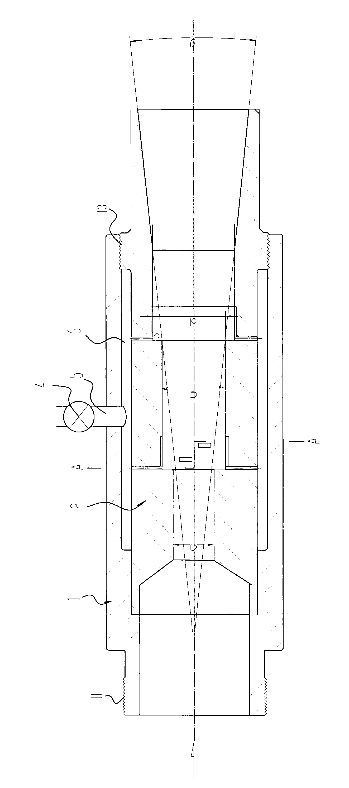
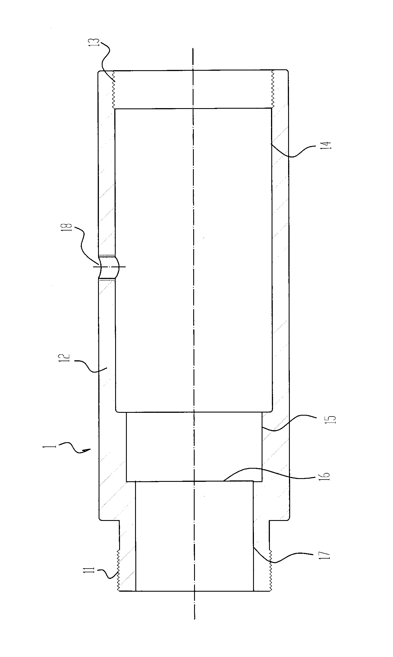
[0031] Embodiment 1, referring to the accompanying drawings listed above. The micro-bubble generating device of the embodiment of the present invention includes a core tube 2 and an outer casing 1, and the water flow direction is set to flow in from the left direction and flow out from the right side;

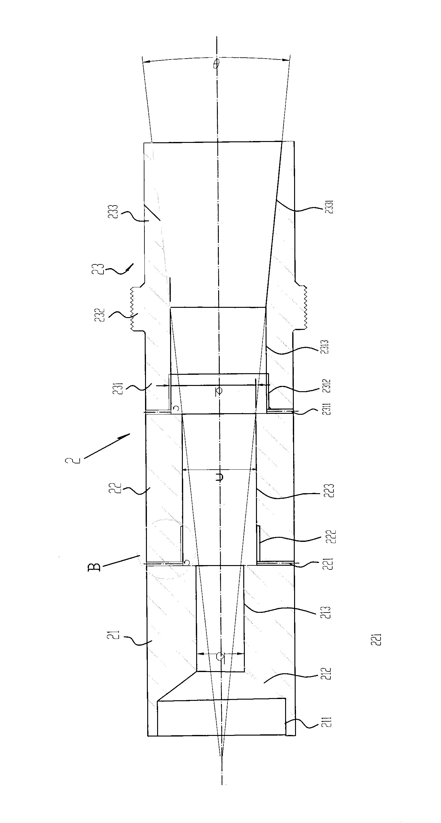
[0032] Wherein the core tube 2 (see image 3 ) includes the following pipe sections located on the same axial line:

[0033] A water suction pipe section 21, the water suction pipe section 21 includes a large cylindrical tube 211, a horn-shaped tube 212 and a small cylindrical tube 213 arranged in sequence from the water inlet direction to the water outlet direction and connected to each other;

[0034] At least one micro-bubble generation pipe section I22, the micro-bubble generation pipe section I22 includes a cylindrical tube 223 with a diameter larger than the diameter of the small cylindrical tube 213 in the above-mentioned water suction pipe section, and also includes at...

Embodiment 2

[0040] Embodiment 2, see again figure 1 . This embodiment is a preferred embodiment. It differs from Embodiment 1 only in that the vent hole 18 on the outer sleeve 1 is a threaded hole that can be connected with the valve adapter 5; in addition,

[0041] A gas regulating valve 4 and a valve connecting pipe 5, the valve connecting pipe 5 is assembled in the aforementioned threaded hole 18, the gas regulating valve 4 is connected in the middle of the valve connecting pipe 5, and a circular ring is formed between the outer sleeve 1 and the core pipe 2 The airtight air chamber 6.

[0042] The number of microbubble generation pipe sections I 22 in the above two embodiments is preferably 2-3; the above-mentioned gas introduction holes 221, 2311 and cutting grooves 222, 2312 are uniformly distributed along the circumference and have the same number, such as Figure 4 The number of gas introduction holes shown is 6, and the number of cutting grooves is 8.

[0043] The cutting groo...


PUM


Abstract

The invention discloses a micro-bubble generation device which aims at solving the defects of high energy consumption and few produced micro-bubbles in the existing device. The micro-bubble generation device comprises an outer sleeve and a core pipe arranged in the outer sleeve, wherein the core pipe comprises a water suction pipe section, at least one micro-bubble generation pipe section I and a micro-bubble injection pipe section; and the micro-bubble injection pipe section comprises a micro-bubble generation pipe section II at a water inlet end, and a loudspeaker-shaped injection pipe which is connected with the micro-bubble generation pipe section II and is positioned at a water outlet end side. The micro-bubble generation pipe sections I and II respectively comprise at least one gas introduction hole and at least one cutting groove. The micro-bubble generation device is used for providing a large number of micro-bubbles in water bodies in purifying tanks, baths, aquiculture pools, sewage treatment plants and the like or liquid in gas-liquid reaction tanks.

Description

technical field [0001] The invention relates to a device for providing fine and a large number of fine air bubbles in water bodies such as water purification tanks, bath tanks, aquaculture ponds, sewage treatment plants, or in the liquid of gas-liquid reaction tanks. Background technique [0002] In recent years, the input and increase of fine air bubbles in water can be used as a means of water purification, an auxiliary means of water purification, a means of increasing the dissolved oxygen in water, or a means of increasing the reaction speed of the gas-liquid reaction tank and improving the reaction efficiency; Or the method of adding fine air bubbles in the pet's bathtub can obtain massage effects, warm effects, cleaning effects, and water purification effects. [0003] Currently, research, development, and commercialization of microbubble generators are in vogue. However, a large number of micro-bubble generating devices need to supply higher water pressure, thereby i...

Claims


Application Information

Patent Timeline
IPC IPC(8): B01F3/04B01F5/00B01F5/02C02F7/00C02F3/02A01K63/04
CPCY02W10/10
Inventor 叶伟才宇家直树
Owner 曾永芳
Why Eureka
Try Eureka