
Gas extraction method by using major diameter pipeline and sealing transverses between mine goaf and tail roadway

A large-diameter pipe and goaf technology is applied in the field of gas extraction in coal mines, and can solve the problems of ineffective interference with the seepage field in the goaf, small drainage flow, and frequent gas overruns.

Inactive Publication Date: 2013-04-17
CHINA UNIV OF MINING & TECH (BEIJING)
View PDF5 Cites 9 Cited by
  • Summary
  • Abstract
  • Description
  • Claims
  • Application Information

AI Technical Summary

Problems solved by technology

[0002] With the complexity of coal mine gas occurrence conditions and people's demand for safe and efficient mining of high-gas mines, the original U+L ventilation system that is more suitable for high-gas coal seam mining can no longer meet the requirements, and the U+L ventilation system is adopted , there are often problems such as the upper corner of the goaf, the gas tail lane and the frequent gas overrun in the return air flow
Existing goaf drainage mainly drains the region where the roof cracks develop in the goaf, and its drainage flow rate is small, which cannot effectively interfere with the seepage field of the goaf
The drainage of buried pipes in the goaf has a great effect on the prevention and control of gas concentration exceeding the limit in the upper corner, but it has a very limited effect on the control of gas concentration exceeding the limit in the tail road

Method used


Image

  • Gas extraction method by using major diameter pipeline and sealing transverses between mine goaf and tail roadway
  • Gas extraction method by using major diameter pipeline and sealing transverses between mine goaf and tail roadway

Examples


Embodiment Construction

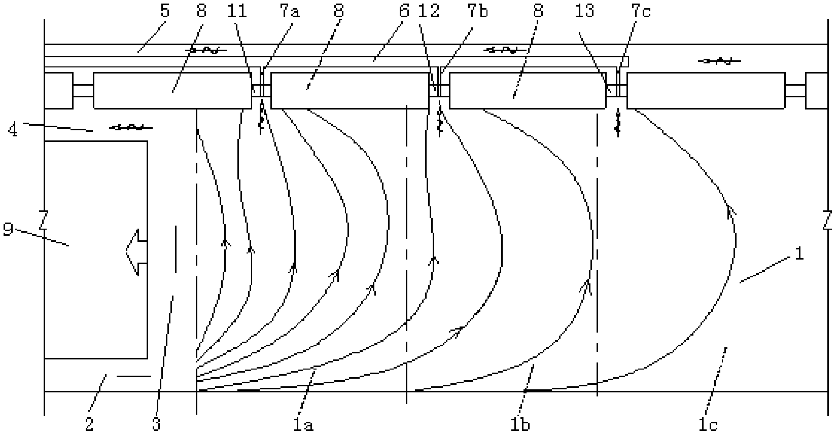
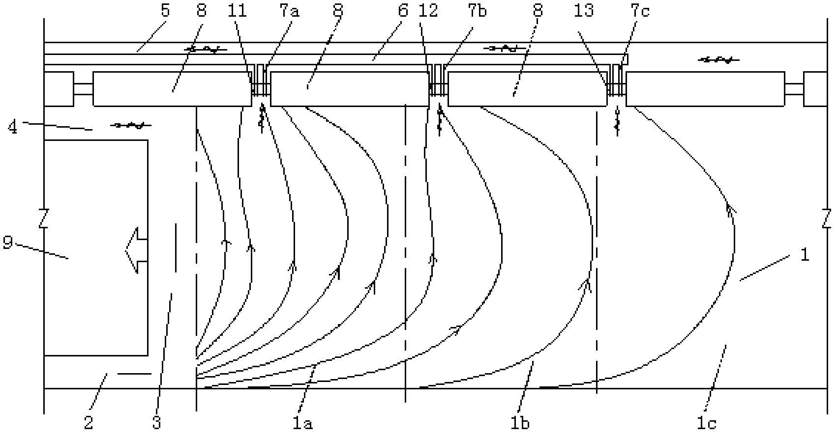
[0019] Such as figure 1 As shown in the structure schematic diagram of the method for the closed gas drainage of the large-diameter pipeline in the tailgate transversely connected to the goaf of the present invention, the method for the closed gas drainage of the large-diameter pipeline in the tailgate transversely connected to the goaf of the present invention includes the following steps step:

[0020] Divide goaf 1 into main extraction sub-area, sub-extraction sub-area and sub-extraction sub-area 1a, 1b, 1c from close to fully mechanized mining face 3 to away from fully mechanized mining face 3;

[0021] Establish a U-shaped gas channel from the air inlet lane 2 to the air return lane 4 via the fully mechanized mining face 3;

[0022] Lay the gas extraction pipeline 6 in the gas tailway 5;

[0023] The closed gas tailgate 5 and the three goaf sub-areas traverse 11, 12, and 13, so that the gas tailgate 5 is isolated from the goaf;

[0024] The branch pipe systems 7a, 7b, ...


PUM

PropertyMeasurementUnit
Lengthaaaaaaaaaa
Diameteraaaaaaaaaa
Diameteraaaaaaaaaa

Abstract

The invention discloses a gas extraction method by using a major diameter pipeline and sealing transverses between a mine goaf and a tail roadway. The method includes the following steps of dividing the mine goaf into a plurality of mine sub-goafs; establishing a first gas channel from an air inlet roadway to an air return roadway through a fully mechanized coal mining face; paving a gas extraction pipeline in a tail gas roadway; sealing the traverses between the tail gas roadway and the plurality of mine sub-goafs; and arranging a plurality of branch pipe systems which are communicated with the gas extraction pipeline in the sealed transverses corresponding to the plurality of mine sub-goafs so as to form a plurality of second gas channels from the air inlet roadway to the gas extraction pipeline through the plurality of mine sub-goafs and the branch pipe systems so that simultaneous extraction of the deep portion of the mine goaf and the neighboring areas of the fully mechanized coal mining face is achieved. By means of the method, the gas amount of an extraction goaf is large, the extraction negative pressure is far higher than ventilation negative pressure, effective interference to gas leakage fields of the mine goaf can be formed, and high concentration gases on deep portions and upper portions of the mine goaf are prevented from inrushing toward upper corner and return current.

Description

technical field [0001] The invention relates to a coal mine gas extraction method, in particular to a coal mine goaf gas extraction method. Background technique [0002] With the complexity of coal mine gas occurrence conditions and people's demand for safe and efficient mining of high-gas mines, the original U+L ventilation system that is more suitable for high-gas coal seam mining can no longer meet the requirements, and the U+L ventilation system is adopted , Frequent problems such as the upper corner of the goaf, the gas tail alley and the return air flow frequently exceed the limit. The existing goaf drainage mainly extracts the goaf roof fissure development area, and its drainage flow rate is small, which cannot effectively interfere with the seepage field of the goaf. The buried pipe drainage in the goaf has a great effect on preventing the gas concentration exceeding the limit in the upper corner, but it has a very limited effect on controlling the gas concentration...

Claims


Application Information

Patent Timeline
IPC IPC(8): E21F7/00
Inventor 何富连谢生荣张守宝
Owner CHINA UNIV OF MINING & TECH (BEIJING)
Learn More