Flow dividing and collecting valve bank, hydraulic system, load sensitive type hydraulic system and engineering machine

It is a technology of dividing and merging and valve group, which is applied to mechanical equipment, fluid pressure actuating devices, servo motor components, etc. It can solve the problem of inability to adapt to the control of load-sensitive hydraulic pumps, complex structure of dividing and merging valves, and unreliable work. problem, to achieve the effect of good automatic adjustment performance and energy saving characteristics, excellent working performance and reliable working performance

Active Publication Date: 2013-04-17
ZOOMLION HEAVY IND CO LTD
View PDF15 Cites 25 Cited by
  • Summary
  • Abstract
  • Description
  • Claims
  • Application Information

AI Technical Summary

Problems solved by technology

In addition, it is known that the load-sensing hydraulic system has good energy-saving and regulating characteristics, and it is widely used in the hydraulic system of construction machinery, but the split-merge valve in the prior art cannot be adapted to the split-merge control of the load-sensing hydraulic pump.
[0004] For example, Chinese invention patent applications CN102094861A and CN102434519A disclose the split-merge hydraulic system, the split-merge valve used in it is not only complicated in structure and unreliable in operation, but only suitable for split-merge control of quantitative pumps, which inevitably has overflow loss. Shortcomings such as system overheating are not suitable for split and confluence control of load-sensing hydraulic systems

Method used


Image

  • Flow dividing and collecting valve bank, hydraulic system, load sensitive type hydraulic system and engineering machine
  • Flow dividing and collecting valve bank, hydraulic system, load sensitive type hydraulic system and engineering machine
  • Flow dividing and collecting valve bank, hydraulic system, load sensitive type hydraulic system and engineering machine

Examples


Embodiment Construction

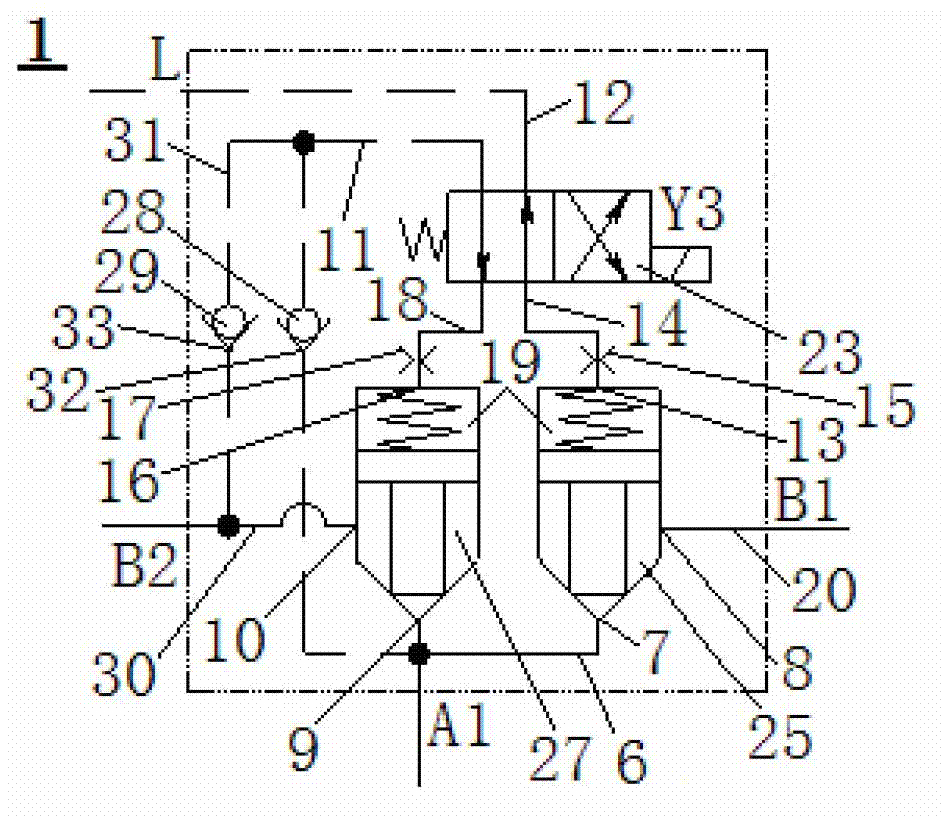
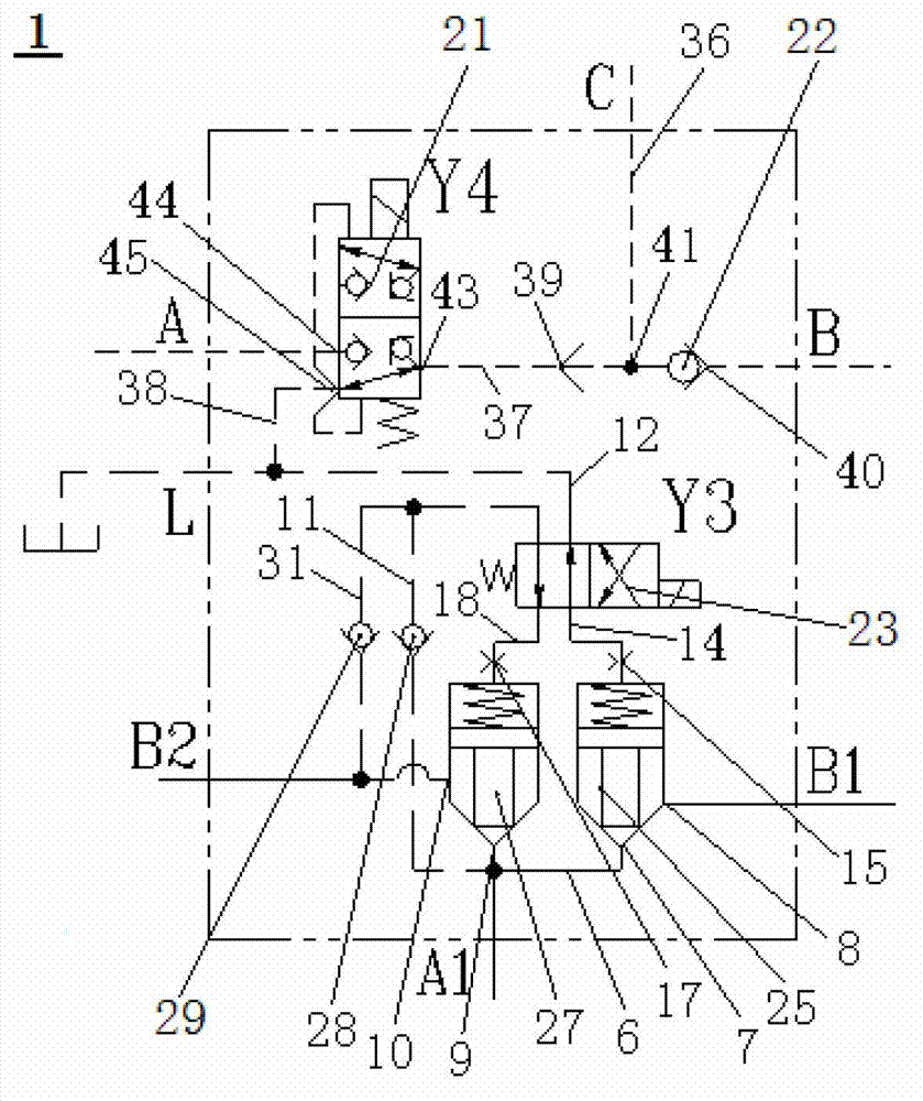
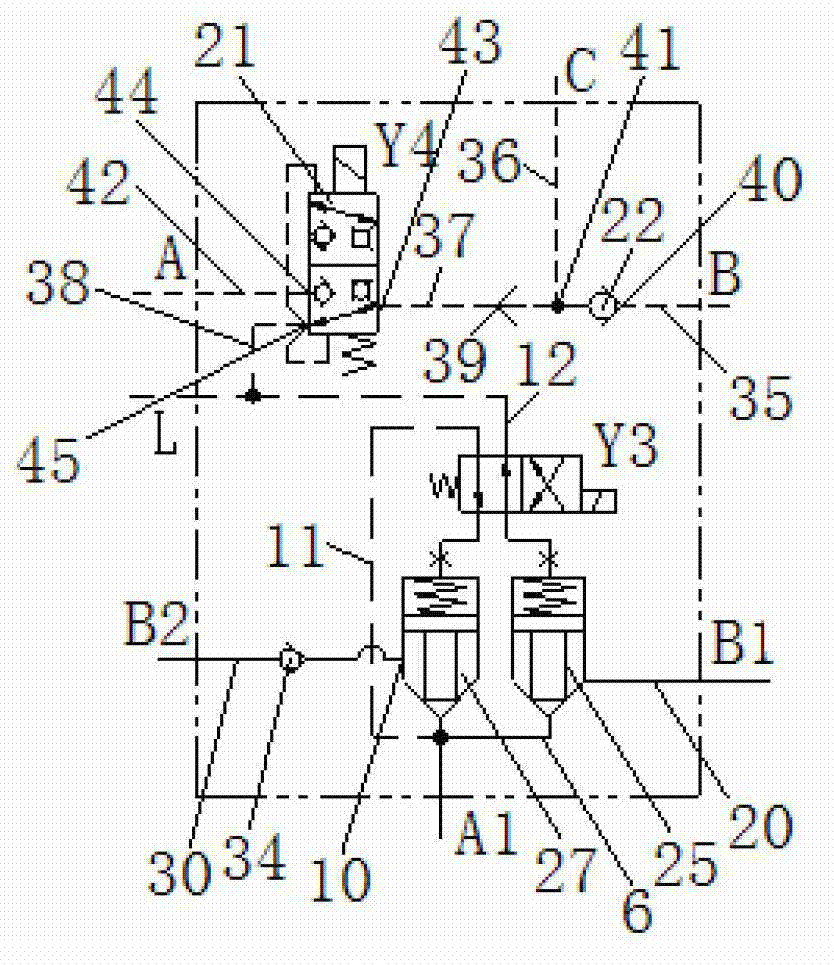
[0058] The specific embodiments of the present invention will be described in detail below in conjunction with the accompanying drawings. It should be understood that the specific embodiments described here are only used to illustrate and explain the present invention, and the protection scope of the present invention is not limited to the following specific embodiments. .

[0059] For those skilled in the hydraulic field, the technical conception of a hydraulic device lies more in its hydraulic connection relationship, and there may be various specific mechanical realization structures. E.g, Figure 1 to Figure 3 The branch and confluence valve group 1 of the specific implementation form shown can be formed as an integral composite valve. In this case, Figure 1 to Figure 3 The corresponding A1, B1, B2, A, B, C and L etc. in can be the corresponding oil ports on the valve body of the integral composite valve, but obviously, Figure 1 to Figure 3 The sub-combination valve gr...


PUM


Abstract

A flow dividing and collecting valve bank comprises a first two-way cartridge valve (25) and a second two-way cartridge valve (27), respective first oil ports ( 7 and 9) of the first two way cartridge-valve (25) and the second two-way cartridge valve (27) are mutually communicated while respective hydraulic control valves (13 and 16) thereof are connected to a reversing valve (23) through a first internal hydraulic control oil way (14) and a second internal hydraulic control oil way (18) respectively, the reversing valve (23) is connected to one end of an internal hydraulic control inlet oil way (11) and one end of an internal hydraulic control return oil way (12), the other end of the internal hydraulic control inlet oil way (11) is communicated with the first oil ports ( 7 and 9), and a second oil port of the second two-way cartridge valve is connected with a flow-collecting oil supply way (30). In addition, the invention further provides a hydraulic system and an engineering machine comprising the flow dividing and collecting valve bank. The flow dividing and collecting valve bank can control flow dividing and collecting of oil supply of different hydraulic pumps as required, and is simple in structure, reliable in working performance and basically free of defects of spill loss, system overheating and the like.

Description

technical field [0001] The invention relates to a diverging and converging valve mainly used on a hydraulic oil supply oil circuit, in particular to a diverging and converging valve group. Further, the present invention relates to a hydraulic system and a load-sensing hydraulic system comprising the split-merge valve group. In addition, the present invention also relates to a construction machine. Background technique [0002] At present, with the development of large-tonnage and super-large-tonnage construction machinery (such as mobile cranes), the working load of construction machinery (such as lifting weight) is increasing, and the corresponding working mechanism of construction machinery, such as the amplitude of the crane Mechanisms, telescopic mechanisms, etc. are also getting bigger and bigger, and the hydraulic oil flow required for the working mechanism to move, especially when it is fast, is also increasing. The hydraulic oil flow output by a single hydraulic pum...

Claims


Application Information

Patent Timeline
Patent Type & Authority Applications(China)
IPC IPC(8): F15B13/02
Inventor 刘琴胡廷江李英智刘建华郭纪梅许俭波
Owner ZOOMLION HEAVY IND CO LTD
Why Eureka
Try Eureka