Stress monitoring method of distributed optical fiber system

A distributed optical fiber and stress monitoring technology, which is applied in the measurement of the change force of the optical properties of the material when it is stressed, can solve the problems of affecting the measurement accuracy, reducing the energy of the pump light, and long detection response time, etc., to achieve Solve the low accuracy of single-frequency scanning, reduce the computational complexity of the system, and improve the effect of measuring the dynamic range

Active Publication Date: 2013-04-17
POWER DISPATCHING CONTROL CENT OF GUANGDONG POWER GRID CO LTD
View PDF6 Cites 15 Cited by
  • Summary
  • Abstract
  • Description
  • Claims
  • Application Information

AI Technical Summary

Problems solved by technology

Distributed optical fiber stress sensing technology based on Rayleigh scattering has the following problems: low accuracy, short sensing distance and long detection response time
In the distributed optical fiber sensing technology based on BOTDR technology and using optical filtering method to detect Brillouin frequency shift, there are mainly the following problems: (1) the self-published Brillouin scattered light generated in the system is relatively weak; (2) the system The medium Brillouin frequency shift is very small, and the measurement is very difficult; (3) Due to the small Brillouin frequency shift, the requirements for the filter are extremely high, and the measurement accuracy is not high, which affects the measurement accuracy; (4) The detection response time is long long
However, such frequency scanning technology takes a long time, cannot achieve real-time detection, and also reduces the accuracy and dynamic range
However, this technol

Method used


Image

  • Stress monitoring method of distributed optical fiber system
  • Stress monitoring method of distributed optical fiber system
  • Stress monitoring method of distributed optical fiber system

Examples


Embodiment Construction

[0028] The technology of measuring Brillouin frequency shift by optical OFDM channel estimation method of the present invention will be described in detail below in conjunction with the accompanying drawings. The following is only used as an example to illustrate, and those skilled in the art clearly know that as long as the method and system conforming to the idea of ​​the present invention are implemented In addition, the scope of protection of the present invention should not be limited only to the measurement of specific parameters of specific structures or components of Brillouin frequency shift technology by means of optical OFDM channel estimation.

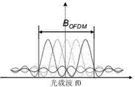
[0029] The present invention adopts optical OFDM channel estimation method to measure Brillouin frequency shift technology. The present invention adopts novel optical channel estimation method for stress measurement, and can complete the scanning of multiple frequency points in one time unit, so that the measurement speed and...


PUM


Abstract

The invention provides a stress monitoring method of a distributed optical fiber system. The method comprises the following steps of: dividing laser into two laser beams, modulating one laser beam with pulse or a random sequence signal into pulse light, and amplifying the pulse light; modulating the other laser beam and an OFDM (orthogonal frequency division multiplexing) signal into a light OFDM signal, and amplifying the light ODFM signal; taking the amplified pulse light as pump light, and the amplified light OFDM signal is taken as detection light; performing Brillouin gain on the two kinds of light in a single mode optical fiber; performing photovoltaic conversion on the pump light and the detection light after subjected to Brillouin gain so as to obtain an OFDM electrical signal; performing channel estimation on the OFDM electrical signal so as to obtain Brillouin frequency shift of each sub-carrier; and acquiring the stress value of each point distributed along an optical fiber axial direction according to the Brillouin frequency shift of each sub-carrier. By the method, the measuring time and precision can be improved; the dynamic range can be greatly improved; the stress monitoring can be performed on power grid system equipment in real time; and the reliability and instantaneity of a distributed sensing system can be improved.

Description

【Technical field】 [0001] The invention relates to the technical field of stress measurement of power systems, in particular to a method for stress monitoring using a distributed optical fiber system. 【Background technique】 [0002] In the power system, cables, wind power equipment, etc. are exposed to the atmosphere for a long time, and are affected by external forces and changes in the external environment, such as wind vibration, ice disaster, dancing, etc., which will cause deformation and sag, which will cause stress and strain in the equipment, and the decrease in equipment strength will cause line interruption and failure. . However, the impact of stress on equipment cannot be shown intuitively. Once the stress accumulates to a certain extent and causes the interruption of equipment work, it will seriously affect the safety of power transmission and power supply in the power system. Preventive measures are very important to improve power system reliability. [0003] ...

Claims


Application Information

Patent Timeline
IPC IPC(8): G01L1/24
Inventor 蒋康明吴赞红黄明辉刘玮刘新展张飞黄达林朱文红潘伟文汪莹
Owner POWER DISPATCHING CONTROL CENT OF GUANGDONG POWER GRID CO LTD
Why Eureka
Try Eureka