Processing method of magnetic powder clutch cup-shaped rotor
A magnetic powder clutch and cup-shaped rotor technology, which is applied in the field of improvement of the processing method of the magnetic powder clutch cup-shaped rotor, can solve the problem of high processing stress, low magnetic permeability of the magnetic powder clutch cup-shaped rotor, and the combination of the working surface of the magnetic powder clutch cup-shaped rotor and the magnetic powder. Force difference and other problems, to achieve the effect of improving magnetic permeability and reducing processing stress
- Summary
- Abstract
- Description
- Claims
- Application Information
AI Technical Summary
Problems solved by technology
Method used
Image
Examples
Embodiment 1
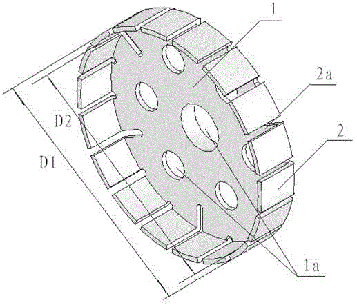
[0031] 1. Rough machining: Use electrical steel DT4E bar stock to carry out rough machining of the cup rotor according to the drawing requirements of the cup rotor to form the blank of the cup rotor. At this time, the hole 1a on the cup bottom 1 of the cup rotor and the upper edge of the cup The gap 2a between adjacent cup fins 2 has been machined and formed, the machining allowance ΔD1=0.6mm for the diameter D1 of the outer circle of the cup-shaped rotor blank is reserved, and the machining allowance ΔD2=0.6mm for the diameter D2 of the inner hole of the cup-shaped rotor blank is reserved mm;
[0032] 2. Hydrogen annealing: Put the cup-shaped rotor blank into a vacuum furnace, heat up to 1150±10°C within 90±5min under a hydrogen atmosphere, keep it warm for 300±5min, and then cool it down to 850±10°C / h at a rate of 100±10°C / h 10°C, keep warm for 180±5min, then cool down to 700°C at a rate of 50±10°C / h, and then cool to room temperature with the furnace;
[0033] 3. Grinding ...
Embodiment 2
[0039] 1. Rough machining: Use electrical steel DT4E bar stock to carry out rough machining of the cup rotor according to the drawing requirements of the cup rotor to form the blank of the cup rotor. At this time, the hole 1a on the cup bottom 1 of the cup rotor and the upper edge of the cup The gap 2a between the adjacent cup fins 2 has been machined, the machining allowance ΔD1=0.5mm for the diameter D1 of the outer circle of the cup-shaped rotor blank is reserved, and the machining allowance ΔD2=0.5mm for the diameter D2 of the inner hole of the cup-shaped rotor blank is reserved mm;
[0040] 2. Hydrogen annealing: Put the cup-shaped rotor blank into a vacuum furnace, heat up to 1150±10°C within 90±5min under a hydrogen atmosphere, keep it warm for 300±5min, and then cool it down to 850±10°C / h at a rate of 100±10°C / h 10°C, keep warm for 180±5min, then cool down to 700°C at a rate of 50±10°C / h, and then cool to room temperature with the furnace;
[0041] 3. Grinding the inn...
Embodiment 3
[0046] 1. Rough machining: Use electrical steel DT4E bar stock to carry out rough machining of the cup rotor according to the drawing requirements of the cup rotor to form the blank of the cup rotor. At this time, the hole 1a on the cup bottom 1 of the cup rotor and the upper edge of the cup The gap 2a between adjacent cup fins 2 has been machined and formed, the machining allowance ΔD1=0.4mm for the diameter D1 of the outer circle of the cup-shaped rotor blank is reserved, and the machining allowance ΔD2=0.4mm for the diameter D2 of the inner hole of the cup-shaped rotor blank is reserved mm;
[0047] 2. Hydrogen annealing: Put the cup-shaped rotor blank into a vacuum furnace, heat up to 1150±10°C within 90±5min under a hydrogen atmosphere, keep it warm for 300±5min, and then cool down to 850±10°C / h at a rate of 100±10°C / h 10°C, keep warm for 180±5min, then cool down to 700°C at a rate of 50±10°C / h, and then cool to room temperature with the furnace;
[0048] 3. Grinding the...
PUM
 Abstract
Description
Claims
Application Information
 - R&D
- Intellectual Property
- Life Sciences
- Materials
- Tech Scout
- Unparalleled Data Quality
- Higher Quality Content
- 60% Fewer Hallucinations
Browse by: Latest US Patents, China's latest patents, Technical Efficacy Thesaurus, Application Domain, Technology Topic, Popular Technical Reports.
© 2025 PatSnap. All rights reserved.Legal|Privacy policy|Modern Slavery Act Transparency Statement|Sitemap|About US| Contact US: help@patsnap.com

