Novel dyeing machine

A dyeing machine and barrel technology, applied in spray/jet textile material treatment, textile material carrier treatment, textile material treatment equipment configuration, etc., can solve the problems of accumulation, increase energy consumption, increase liquor ratio, etc., and achieve uniform dyeing, The effect of reducing the liquor ratio and reducing the running weight

Active Publication Date: 2015-06-17
广州市番禺艺煌洗染设备制造有限公司
View PDF7 Cites 0 Cited by
  • Summary
  • Abstract
  • Description
  • Claims
  • Application Information

AI Technical Summary

Problems solved by technology

In the prior art, the swing tube is a circular arc bend structure with openings at both ends. The swing tube with this structure has the following defects in actual use, that is, the dye liquor will fall down along the cloth outlet of the swing tube and enter In the cloth collection bin, and accumulate in the lower part of the cloth collection bin, this increases the bath ratio and increases energy consumption

Method used


Image

  • Novel dyeing machine
  • Novel dyeing machine
  • Novel dyeing machine

Examples


Embodiment 1

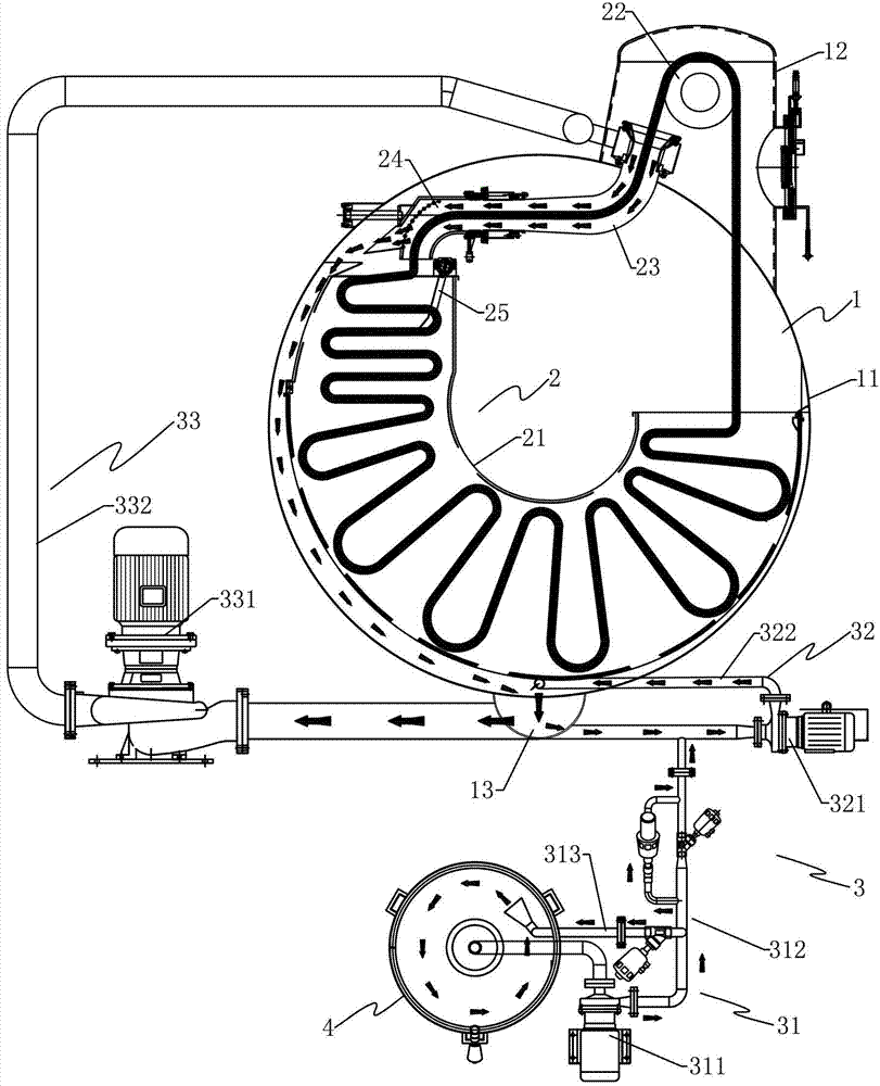
[0025] Such as Figures 1 to 3 As shown, the dyeing machine of the present invention includes an organic barrel 1 , a cloth moving system 2 and a mixing system 3 .

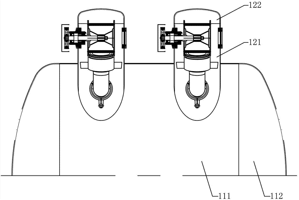
[0026] The above-mentioned machine barrel 1 includes a transverse barrel 11 and a cylinder head 12. The transverse barrel 11 is mainly composed of a middle barrel 111 and THA heads 112 on both sides. The cylinder head 12 is mainly composed of an elliptical connecting pipe 121 and a flat head 122. Wherein, the elliptical connecting pipe 121 of the cylinder head 12 is sealed and connected with the middle cylinder 111 of the transverse cylinder 11 to form an integral machine barrel 1; furthermore, a water collection tank 13 is arranged at the bottom of the machine barrel 1, and a mixing bucket 4 is arranged outside.

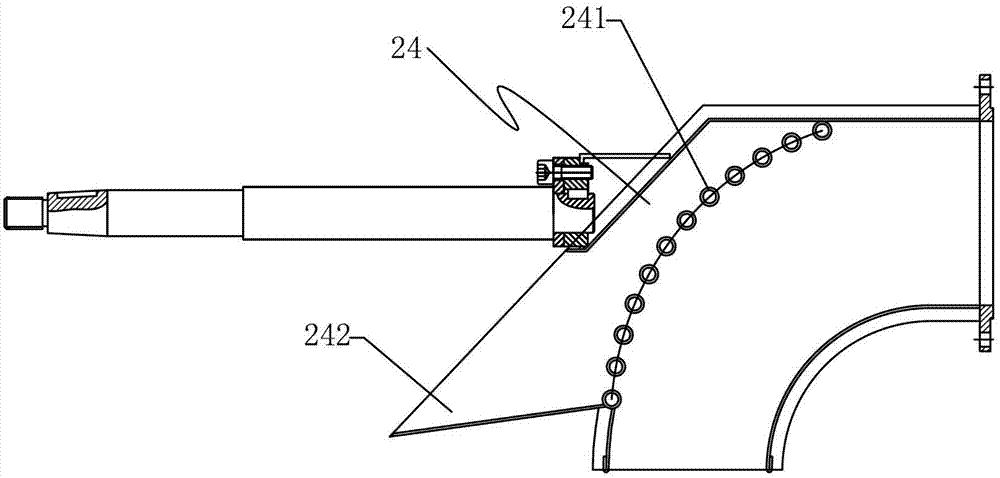
[0027] The above-mentioned cloth running system 2 includes a cloth collecting bin 21, a cloth lifting wheel 22, a cloth guide pipe 23, a horizontal distribution pipe 24, and an upper and lower distribut...

Embodiment 2

[0031] Such as Figure 4 As shown, the embodiment described in this embodiment is basically the same as that of Embodiment 1, the only difference being that the barrel 1 is provided with a wheel shell 5 outside, and the wheel shell 5 is connected to the barrel 1 through a connecting pipe 51, The cloth collecting bin 21, the cloth guide pipe 23, the horizontal distribution pipe 24, the upper and lower distribution plates 25 of the cloth running system 2 are located in the barrel 1, and the cloth lifting wheel 22 is located in the wheel shell 5, that is, the cloth lifting wheel 22 is placed outside the Barrel 1.


PUM


Abstract

The invention discloses a novel dyeing machine comprising a cylinder, a routing system and a material mixing system, wherein a header tank is arranged at the bottom part of the cylinder; a material mixing bucket is arranged at the external part of the cylinder; the routing system comprises a cloth collecting bin, a cloth lifting wheel, a cloth guide tube and a horizontal cloth placement tube; a nozzle is arranged at the cloth guide tube; the horizontal cloth placement tube is of an arc elbow structure; an outer arc turning part adopts a hollow permeable structure; a liquid outlet extends towards the direction of the cylinder around the hollow permeable structure; the material mixing system comprises a first material mixing branch, a second material mixing branch and a third material mixing branch, wherein an inlet of the first material mixing branch is connected with the material mixing bucket; an outlet of the first material mixing branch is connected to the material mixing branch; an inlet of the second material mixing branch is connected to the bottom part of the header tank; an outlet of the second material mixing branch is connected with the bottom part of the cylinder; an inlet of the third material mixing branch is connected with the header tank, and an outlet of the third material mixing branch is connected with the nozzle. According to the novel dyeing machine, the dyeing is even; the bath ratio is effectively reduced; the surface effect of the cloth is improved, and the novel dyeing machine has good economic benefits.

Description

technical field [0001] The invention relates to a dyeing machine, which belongs to the technical field of dyeing equipment, in particular to an environmentally friendly, energy-saving and high-efficiency dyeing machine. Background technique [0002] In the technical field of dyeing equipment, dyeing machines are all equipped with a mixing system. The general structure is to use a mixing tank, and the dye solution in the mixing tank is directly pumped to the nozzle through a water pump and a connecting pipeline for spraying cloth. Although the structure of this mixing system is simple, it has a big defect, that is, the color of the dye solution in the mixing tank is relatively dark. If it is directly sprayed on the fabric, it is easy to produce dark blocks, and the color is uneven, and the dyeing effect of the fabric will be reduced. Not ideal, especially for some fabrics that need to be lightly dyed. [0003] On the other hand, the dyeing machine is also equipped with a clo...

Claims


Application Information

Patent Timeline
Patent Type & Authority Patents(China)
IPC IPC(8): D06B1/02D06B23/20D06B23/04
Inventor 何达广
Owner 广州市番禺艺煌洗染设备制造有限公司
Why Eureka
Try Eureka