A four-cylinder hydraulic pumping unit

A technology of pumping unit and hydraulic oil pump, which is applied in the fields of production fluid, wellbore/well parts, earthwork drilling and production, etc. It can solve the difficulties of long stroke, poor stress condition of the whole machine, installation, transportation and well site layout. and other issues to achieve the effect of improving oil pumping efficiency and reducing energy consumption

Active Publication Date: 2015-09-02
无锡市科优液压设备制造有限公司
View PDF7 Cites 0 Cited by
  • Summary
  • Abstract
  • Description
  • Claims
  • Application Information

AI Technical Summary

Problems solved by technology

[0003] In order to exploit deep oil wells and heavy oil wells, pumping units with large loads must be used, so it is necessary to develop long-stroke and large-load pumping units. Although the beam pumping unit has the advantages of simple structure and easy maintenance, it is the current traditional It is the most widely used pumping unit in the world, but there are many problems in the design of long stroke and large load. 1. The size of the mechanism is too large. For example, the weight of the whole machine of the 12-type pump is about 34 tons; 2. The balance is poor, and the length of the beam exceeds 9 meters. The weight of the balance part is also more than 10 tons. 3 Due to the increase in size, the force condition of the whole machine is also worse. These bring difficulties to installation, transportation and well site layout
It can be seen that the conventional kowtow machine is difficult to meet the requirements of long stroke, low stroke and large load
[0004] In order to solve the above technical problems, people have designed hydraulic oil pumping equipment to replace the traditional kowtow machine. The existing hydraulic oil pumping units generally use a single working hydraulic cylinder, and the gravitational potential energy of the well rod cannot be effectively recovered, resulting in Increased energy consumption, room for improvement

Method used


Image

  • A four-cylinder hydraulic pumping unit
  • A four-cylinder hydraulic pumping unit
  • A four-cylinder hydraulic pumping unit

Examples


Embodiment 1

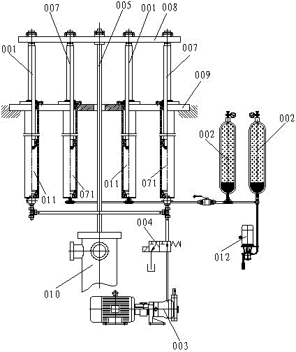
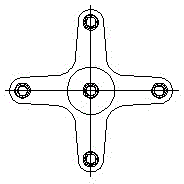
[0016] Embodiment 1: A four-cylinder hydraulic pumping unit, including two working cylinders 001, an accumulator 002, a hydraulic oil pump 003, a reversing valve 004, and a pumping well rod 005, and the working cylinder 001 is connected with a rodless chamber 011 The hydraulic oil pump 003 is provided with a reversing valve 006 on the pipeline, and also includes two balance oil cylinders 007. The working oil cylinder 001 and the balance oil cylinder 007 surround the well rod 005 in a symmetrical cross shape in pairs. The working oil cylinder 001, The piston rod of the balance oil cylinder 007 and the well rod 005 are fixedly connected to the connecting frame 008, and the cylinder bodies of the working oil cylinder 001 and the balance oil cylinder 007 are fixed on the workbench 009. The well rod 005 extends into the oil well 010 through the through hole. The rodless chamber 071 of the balance cylinder 007 is connected to the accumulator 002 by a pipeline. The pipeline is also pr...

Embodiment 2

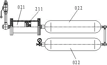
[0017] Embodiment 2: Referring to Embodiment 1, the accumulator 002 is composed of a transfer cylinder 021 and a pressure gas cylinder 022 connected sequentially by pipelines, and the transfer cylinder 021 is provided with a piston 211 to separate the cylinder into two sealed cavities .


PUM


Abstract

A four-cylinder type hydraulic pumping unit comprises two operating cylinders, energy accumulators, a hydraulic oil pump, a reversing valve and a pumping well rod, wherein rodless chambers of the operating cylinders are connected with the hydraulic oil pump through a pipeline provided with the reversing valve. The four-cylinder type hydraulic pumping unit is characterized by further comprising two balance cylinders, the operating cylinders and the balance cylinders symmetrically and crossly enclose the well rod in pairwise, piston rods of the operating cylinders and the balance cylinders and the well rod are fixedly connected onto a connecting frame, cylinder blocks of the operating cylinders and the balance cylinders are fixed on a workbench, a through hole allowing the well rod to penetrate through is arranged on the workbench, the well rod extends into the oil well, and rodless chambers of the balance cylinders are connected with the energy accumulators through a pipeline additionally provided with an oil way which is connected with a small hydraulic oil pump. Pressure of the energy accumulators enables the balance cylinders to generate upward thrust, so that the mass of the well rod is counteracted, and further, gravitational potential energy of the well rod is recovered, energy consumption is reduced greatly, and pumping efficiency is improved.

Description

technical field [0001] The invention relates to oil pumping equipment used in oil fields, in particular to a four-cylinder hydraulic pumping unit. Background technique [0002] Most of the oilfields in the world today use rod-type pumping units, which pump crude oil to the ground by driving the sucker rod to reciprocate the plunger of the downhole pump. Since the depth of the oil well is usually thousands of meters, the weight of the sucker rod also varies with the depth of the oil well. According to current investigations in various oil fields in China and Southeast Asia, most of them are in the range of 5-15 tons. Now the oil field routinely uses beam-type mechanical pumping units (commonly known as kowtow machines). [0003] In order to exploit deep oil wells and heavy oil wells, pumping units with large loads must be used, so it is necessary to develop long-stroke and large-load pumping units. Although the beam pumping unit has the advantages of simple structure and eas...

Claims


Application Information

Patent Timeline
Patent Type & Authority Patents(China)
IPC IPC(8): E21B43/00
Inventor 钱雪强邵建辉周幼海
Owner 无锡市科优液压设备制造有限公司
Why Eureka
Try Eureka