One-chip latch type Hall sensor

A Hall sensor, single-chip technology, applied in the field of single-chip latch Hall sensors, can solve the problems of Hall plate sensitivity reduction, affecting signal establishment accuracy, sampling signal establishment accuracy deviation, etc., to achieve sensitivity temperature The drift effect is reduced and the effect of avoiding the charge injection effect

Inactive Publication Date: 2013-04-24
上海腾怡半导体有限公司
View PDF8 Cites 6 Cited by
  • Summary
  • Abstract
  • Description
  • Claims
  • Application Information

AI Technical Summary

Problems solved by technology

[0006] First, the switches M1 and M2 are directly connected to the sampling capacitor C 1 、C 2 On the upper plate, when the switches M1 and M2 are turned off, due to the influence of charge injection and clock feedthrough effect, it will directly lead to a deviation in the establishment accuracy of the sampling signal;
[0007] Secondly, the kickback noise at the switching instant of switches M1 and M2 will be directly coupled back to the reference voltage V 2 , V 1 On the other hand, the reference voltage changes instantly when the switches M1 and M2 are switched. If the recovery time is not enough, it will also affect the establishment accuracy of the signal;
[0008] Finally, since the sensitivity of the Hall plate will decrease with the increase of temperature, it will reduce the stability of the hysteresis interval with temperature

Method used


Image

  • One-chip latch type Hall sensor
  • One-chip latch type Hall sensor
  • One-chip latch type Hall sensor

Examples


Embodiment Construction

[0033] According to the accompanying drawings, preferred embodiments and alternative embodiments of the present invention are given below, and described in detail, so as to better understand the functions and characteristics of the present invention.

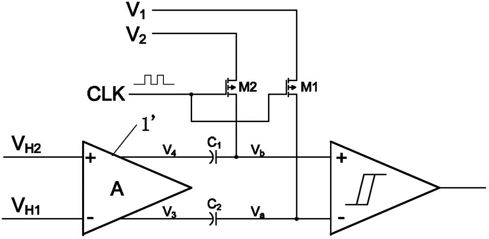
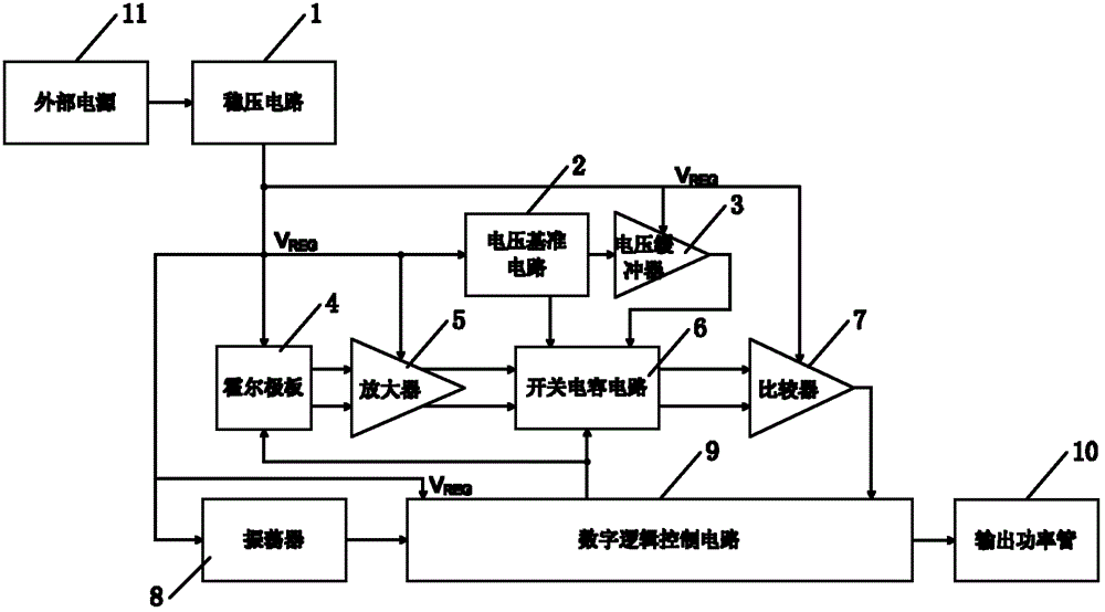
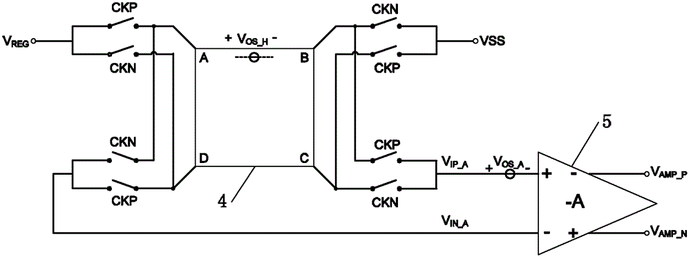
[0034] Such as figure 2 As shown, the present invention, that is, a single-chip latch-type Hall sensor, includes a voltage stabilizing circuit 1, a voltage reference circuit 2, a voltage buffer 3, a Hall plate 4, an amplifier 5, a switched capacitor circuit 6, and a comparison Device 7, oscillator 8, digital logic control circuit 9 and output power tube 10.

[0035] The voltage stabilizing circuit 1 is used to convert the voltage of the external power supply 11 into the internal power supply V REGvoltage, and supply power to voltage reference circuit 2, voltage buffer 3, Hall plate 4, amplifier 5, comparator 7, oscillator 8 and digital logic control circuit 9 respectively, the internal power supply V REG The voltage is not af...


PUM


Abstract

The invention relates to a one-chip latch type Hall sensor which comprises a Hall counter electrode, an amplifier, a switched capacitance circuit and a comparator, wherein the Hall counter electrode, the amplifier, the switched capacitance circuit and the comparator are sequentially connected. The one-chip latch type Hall sensor further comprises a voltage reference circuit which is connected with the switched capacitance circuit, wherein the Hall counter electrode is controlled by a first clock signal and a second clock signal, the first clock signal and the second clock signal are input from outside, the switched capacitance circuit comprises a first capacitor, a second capacitor, a third capacitor and a fourth capacitor, the first capacitor, the second capacitor, the third capacitor and the fourth capacitor are respectively provided with an upper counter electrode and a lower counter electrode, and the first clock and the second clock signal are two-phase clock signals which are non-overlapped. Due to the fact that the second capacitor and the third capacitor sample a Hall signal which is amplified by the amplifier, the first capacitor and the fourth capacitor sample reference voltages which are output by the voltage reference circuit, and meanwhile a third clock signal is introduced under the condition of sampling of the first capacitor, the second capacitor, the third capacitor and the fourth capacitor, influence of a charge injection effect and a clock feed through effect on signal establishing accuracy in the moment of switching a sampling switch is avoided.

Description

technical field [0001] The invention relates to a single-chip latch type Hall sensor. Background technique [0002] In recent years, brushless DC motors have been widely used in aerospace systems, national defense and military equipment, scientific instruments, industrial automation equipment, medical equipment, household appliances and consumer products, and are considered to be the most promising and promising motor in the 21st century. Electronically controlled motors with broad application prospects. As the core component, the Hall sensor plays an increasingly important role. To a large extent, the performance of the Hall sensor directly determines the quality of the brushless DC motor. [0003] The development of semiconductor technology has made it possible to manufacture highly integrated monolithic Hall sensors. However, due to some unavoidable factors in the semiconductor manufacturing process and chip packaging process, Hall sensors will have a high fixed offset v...

Claims


Application Information

Patent Timeline
IPC IPC(8): G01D3/02G01D3/036
Inventor 黄颖彭卓贾晓钦陈忠志
Owner 上海腾怡半导体有限公司
Why Eureka
Try Eureka