Digital pulse power supply synchronous timing trigger system

A digital pulse and power synchronization technology, which is applied in general control systems, control/regulation systems, instruments, etc., can solve the problems of low real-time processing capability and flexibility, inability to realize synchronous timing trigger system control, and inability to realize multiple triggers or multiple Various device group triggers and other issues, to achieve the effect of high real-time processing capability, high integration, and short development cycle

Active Publication Date: 2013-04-24
INST OF MODERN PHYSICS CHINESE ACADEMY OF SCI
View PDF4 Cites 9 Cited by
  • Summary
  • Abstract
  • Description
  • Claims
  • Application Information

AI Technical Summary

Problems solved by technology

4: The FPGA in the timing trigger system mentioned only implements timing frequency division and single pulse delay triggering
The system is a single-pulse delay timing trigger system, which mainly realizes the timing control function of the equipment. The system function is mainly realized by single-pulse and FPGA trigger delay. The microprocessor is an 8-bit single-chip microcomputer, and the network communication is 10M

Method used


Image

  • Digital pulse power supply synchronous timing trigger system
  • Digital pulse power supply synchronous timing trigger system
  • Digital pulse power supply synchronous timing trigger system

Examples


Embodiment Construction

[0027] The principles and features of the present invention are described below in conjunction with the accompanying drawings, and the examples given are only used to explain the present invention, and are not intended to limit the scope of the present invention.

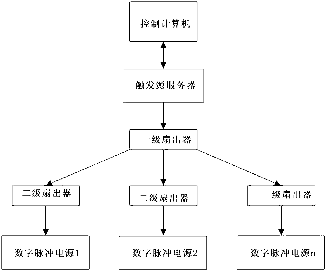
[0028] Such as figure 1 As shown, the digital pulse power supply synchronous timing trigger system is characterized in that it includes a trigger source server interconnected with a control computer with a field programmable gate array FPGA as hardware, the trigger source server is connected with a first-level fan-out device, and the first-level The fan-outs are respectively connected to multiple secondary fan-outs without time difference, and the secondary fan-outs are connected to the digital pulse power supply module. There is a time difference between the primary fan-out device and the secondary fan-out device. This time difference is the receiving and sending time of the data frame between them. This time can be ...


PUM


Abstract

The invention relates to a digital pulse power supply synchronous timing trigger system for achieving a remote synchronous timing trigger control with many sets of digital pulse power supply.. The digital pulse power supply synchronous timing trigger system is characterized in that the trigger system comprises a trigger source server and the trigger source server is mutually connected with a control computer, the hardware of the trigger source server is a field programmable gata array (FPGA). The trigger source server is connected with a first-level fan-out machine which is respectively connected with multichannel second fan-out machines without time differences. The second fan-out machine is connected with a digital pulse power supply module. The digital pulse power supply synchronous timing trigger system achieves the synchronous starting or the grouped synchronous starting control of ion accelerator digital pulse power supply or related industry many sets of digital pulse power supply according to the setting time series. And the digital pulse power supply synchronous timing trigger system meets the requirements that the digital pulse power in the relevant fields can be started flexible timing synchronization under the remote control method.

Description

technical field [0001] The invention relates to a digital pulse power supply synchronous timing trigger system for realizing remote synchronous timing trigger control of multiple digital pulse power supplies. Background technique [0002] The synchronous system is also called the synchronous trigger system. It generates a series of time reference pulses and transmits these pulses to all power supplies that need to work synchronously without time difference. The power supply that receives the synchronous signal is triggered by the synchronous pulse. Run in a set manner according to the set timing relationship. [0003] With the development of digital technology, it becomes possible for digital pulse power supplies to be used in the field of ion accelerators. In particle accelerators, especially synchrotrons, multiple digital pulse power Triggered at a specified time interval and run synchronously in a specified mode. Conventional systems that deliver single-shot triggers ca...

Claims


Application Information

Patent Timeline
IPC IPC(8): G05B19/042
Inventor 赵江陈又新原有进高大庆王荣坤闫怀海周忠祖吴凤军黄玉珍燕宏斌冯秀明张华剑高亚林
Owner INST OF MODERN PHYSICS CHINESE ACADEMY OF SCI
Why Eureka
Try Eureka