Backlight driving circuit and liquid crystal display

A technology of backlight driving circuit and circuit, which is applied in the direction of static indicator, lamp circuit layout, light source, etc., can solve the problems of current precision drop, resistance influence, current precision influence, etc., and achieve the effect of improving precision

Active Publication Date: 2013-04-24
SHENZHEN CHINA STAR OPTOELECTRONICS TECH CO LTD
View PDF6 Cites 16 Cited by
  • Summary
  • Abstract
  • Description
  • Claims
  • Application Information

AI Technical Summary

Problems solved by technology

[0004] In addition, the circuit further includes a current setting circuit, the current setting circuit includes a triode Q3, and parallel resistors R1 and R2 are connected between its collector and the ground, then the resistance after parallel connection is R=(R1* R2)/(R1+R2), it can be seen from this that if the resistance values ​​of the resistors R1

Method used


Image

  • Backlight driving circuit and liquid crystal display
  • Backlight driving circuit and liquid crystal display
  • Backlight driving circuit and liquid crystal display

Examples


no. 1 example

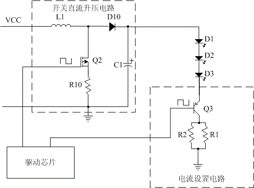
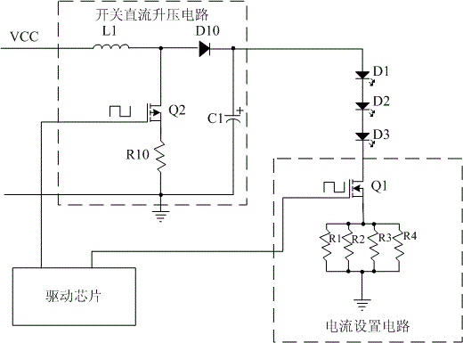
[0039] The present invention provides a circuit for backlight driving, such as figure 2 As shown, the first embodiment of the present invention is shown, the backlight drive circuit includes:

[0040] A voltage stabilizing circuit that receives an input voltage, filters the input voltage, and outputs a regulated DC power, wherein the voltage stabilizing circuit is a capacitor C2 connected between the input voltage and ground, and the input voltage can be a DC voltage such as 24V or 48V ;

[0041] The boost circuit is connected to the voltage stabilizing circuit, and is connected to the positive end of the light-emitting diode LED light bar, and is used to receive the regulated direct current, boost the voltage and output it to the light-emitting diode LED light bar;

[0042] A current setting circuit, connected to the negative terminal of the light-emitting diode LED light bar, is used to set the current for the light-emitting diode LED light bar;

[0043] A control circuit...


PUM


Abstract

The invention discloses a backlight driving circuit. The backlight driving circuit comprises a voltage stabilizing circuit, a boost circuit and a control circuit. The voltage stabilizing circuit receives input voltage, filters the input voltage and outputs voltage stabilizing direct current. The boost circuit is connected with the voltage stabilizing circuit, receives the voltage stabilizing direct current, boosts and outputs the voltage stabilizing direct current to a light emitting diode (LED) light bar. The control circuit is connected with the boost circuit and is used for supplying a pulse width modulation (PWM) square wave and controlling the boost circuit to supply power for the LED light bar. The boost circuit comprises a metal oxide semiconductor (MOS) pipe or an audion. At least three resistors with near or same value of resistance are in parallel connection between a source electrode of the MOS pipe or a collector of the audion and the ground. Accordingly, the invention further provides a liquid crystal display adopting the backlight driving circuit. The backlight driving circuit and the liquid crystal display can improve the accuracy of the current output to the LED light bar.

Description

technical field [0001] The present invention relates to the field of liquid crystal displays, in particular to a backlight drive circuit and a liquid crystal display. Background technique [0002] In the prior art light emitting diode (Light Emitting Diode, LED) backlight driving circuit of a liquid crystal display, a Boost circuit (the boost converter or step-up converter, switching DC boost circuit) is usually used to supply power to the LED. [0003] Such as figure 1 As shown, the inductor L1, diode D10, resistor R10, capacitor C1, and MOS tube (Metal-Oxide-Semiconductor Field Effect Transistor, Metal-Oxide-Semiconductor Field Effect Transistor) Q2 in the virtual frame form a Boost circuit, which is provided by the driver chip The PWM signal controls the MOS tube Q2. When the MOS tube is turned on, the capacitor C1 supplies power to the LED light bar, and the source of the MOS tube is grounded through the resistor R10. [0004] In addition, the circuit further includes ...

Claims


Application Information

Patent Timeline
IPC IPC(8): G09G3/34G09G3/36
CPCG09G3/36H05B37/02G09G3/3406G09G2320/064G09G2330/021H05B45/38
Inventor 张先明
Owner SHENZHEN CHINA STAR OPTOELECTRONICS TECH CO LTD
Why Eureka
Try Eureka