
Fuel tank for direct liquid fuel battery system with self-closing interface

A liquid fuel cell and fuel tank technology, applied in the direction of fuel cell additives, etc., can solve the problems of fuel supply cut-off and incomplete fuel follow-up, and achieve the effect of convenient operation and avoiding system shutdown operation

Active Publication Date: 2014-12-24
孙公权
View PDF5 Cites 0 Cited by
  • Summary
  • Abstract
  • Description
  • Claims
  • Application Information

AI Technical Summary

Problems solved by technology

[0004] At present, in order to meet the miniaturization requirements of portable fuel cells, researchers try to integrate the fuel cartridge into the fuel cell system, and some researchers use capillary force to supply liquid fuel from the fuel tank to the fuel electrode, but the fuel is directly supplied to the fuel in a liquid state. Therefore, when mounted in a small portable device, in a use environment where the front, rear, left, right, or up and down of the battery unit are constantly changing, during long-term use, the following problems of fuel may be incomplete, and the fuel supply may be cut off.

Method used


Image

  • Fuel tank for direct liquid fuel battery system with self-closing interface
  • Fuel tank for direct liquid fuel battery system with self-closing interface
  • Fuel tank for direct liquid fuel battery system with self-closing interface

Examples


Embodiment Construction

[0030] The present invention will be further described below in conjunction with the accompanying drawings.

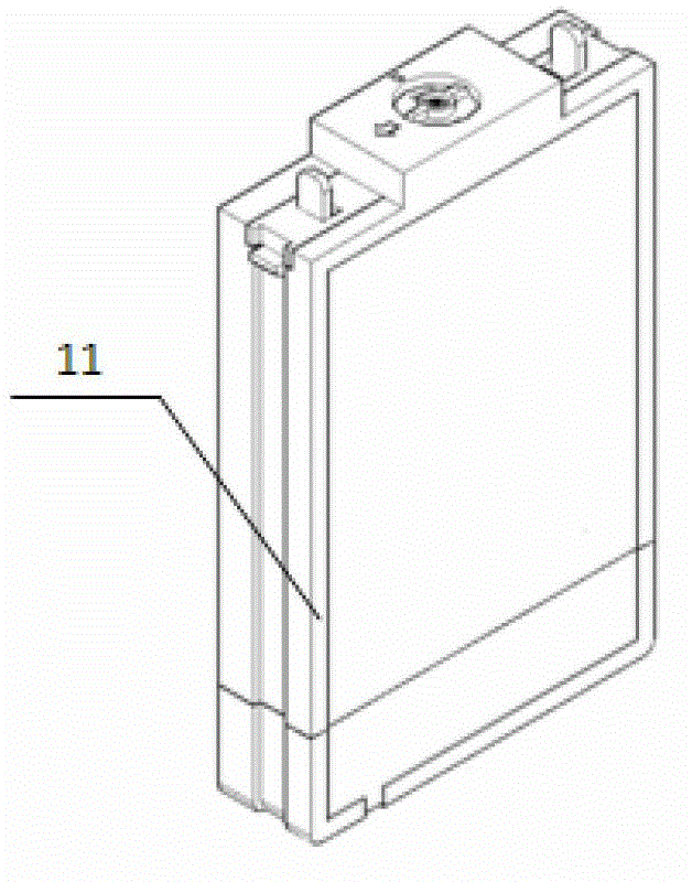
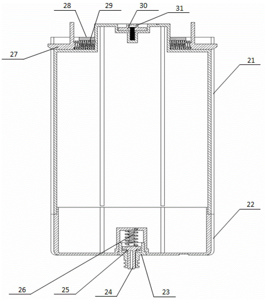
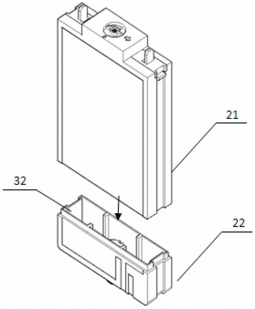
[0031] Such as figure 2 , image 3 and Figure 6 As shown, the present invention includes a fuel tank body, a Kafun mechanism, a screw seal cap 30 and a self-closing interface, wherein the fuel tank body is a flat structure, including an upper fuel tank body 21 and a lower fuel tank body 22, and an upper fuel tank body 21 and a lower fuel tank body 22. The lower fuel tank body 22 is positioned through the seam 32, and is connected by ultrasonic welding or bonded and sealed by bonding. The adhesive used may be chloroform or acetone. The fuel tank is made of methanol-resistant PC (polycarbonate) or PEI (polyetherimide). The upper end of the upper fuel tank body 21 is respectively provided with a screw sealing cover 30 and a Kafun mechanism connected with an external mounting body and restricting the movement of the fuel tank body. The self-closing interface is arran...


PUM


Abstract

The invention belongs to the technical field of direct liquid fuel battery systems, and particularly discloses a fuel tank for a direct liquid fuel battery system with a self-closing interface. The fuel tank comprises a fuel tank body, a falcon clamping mechanism, a spiral sealing cover and the self-closing interface, wherein the upper end of the fuel tank body is respectively provided with the spiral sealing cover and the falcon clamping mechanism; the self-closing interface is formed in the bottom of the fuel tank body and comprises an external interface, an inner core and a sealing spring, wherein one end of the external interface is connected with an interface fixing hole formed in the lower part of the fuel tank body, and the other end of the external interface is connected with an external interface hole formed in an external installation body; one end of the inner core is inserted into the external interface from one end of the external interface, the other end of the inner core is positioned by a rabbet on the external interface, the sealing spring is contained in the interface fixing hole, one end of the sealing spring is connected with the bottom of the interface fixing hole in a propping manner, and the other end of the sealing spring is connected with the other end of the inner core in the propping manner; and the inner core can slide in the external interface in a reciprocating manner along the axial direction under the action of external force or the sealing spring, and the other end of the inner core and the rabbet on the external interface are departed or are connected in a sealing manner. The fuel tank provided by the invention avoids fuel leakage in a storage and assembly process.

Description

[0001] technical field [0002] The invention belongs to the technical field of direct liquid fuel cell systems, in particular to a fuel tank for direct liquid fuel cell systems with a self-closing interface. Background technique [0003] A direct liquid fuel cell is a chemical reaction device that converts chemical energy in liquid fuel (such as methanol, ethanol, etc.) directly into electrical energy. Due to the high specific energy of liquid fuels such as methanol and ethanol, and the advantages of simple structure of the fuel cell system, this type of battery has broad application prospects in the field of portable mobile power. [0004] At present, in order to meet the miniaturization requirements of portable fuel cells, researchers try to integrate the fuel cartridge into the fuel cell system, and some researchers use capillary force to supply liquid fuel from the fuel tank to the fuel electrode, but the fuel is directly supplied to the fuel in a liquid state. Therefore...

Claims


Application Information

Patent Timeline
Patent Type & Authority Patents(China)
IPC IPC(8): H01M8/04
CPCY02E60/50
Inventor 孙公权
Owner 孙公权
Learn More