Battery pole group welding device and method

A battery electrode group and electrode group technology, which is applied in the field of battery electrode group welding devices, can solve problems such as labor-intensive, low production efficiency, and cumbersome processes, so as to reduce product failure rate, improve production efficiency, and reduce production costs. cost effect

Active Publication Date: 2013-05-01
ZHAOQING LEOCH BATTERY TECH
View PDF6 Cites 8 Cited by
  • Summary
  • Abstract
  • Description
  • Claims
  • Application Information

AI Technical Summary

Problems solved by technology

This process is cumbersome, consumes a lot of labor, and the production efficiency is low. In addition, the separator is easily pierced by the pole plate ...

Method used


Image

  • Battery pole group welding device and method
  • Battery pole group welding device and method
  • Battery pole group welding device and method

Examples


Embodiment 1

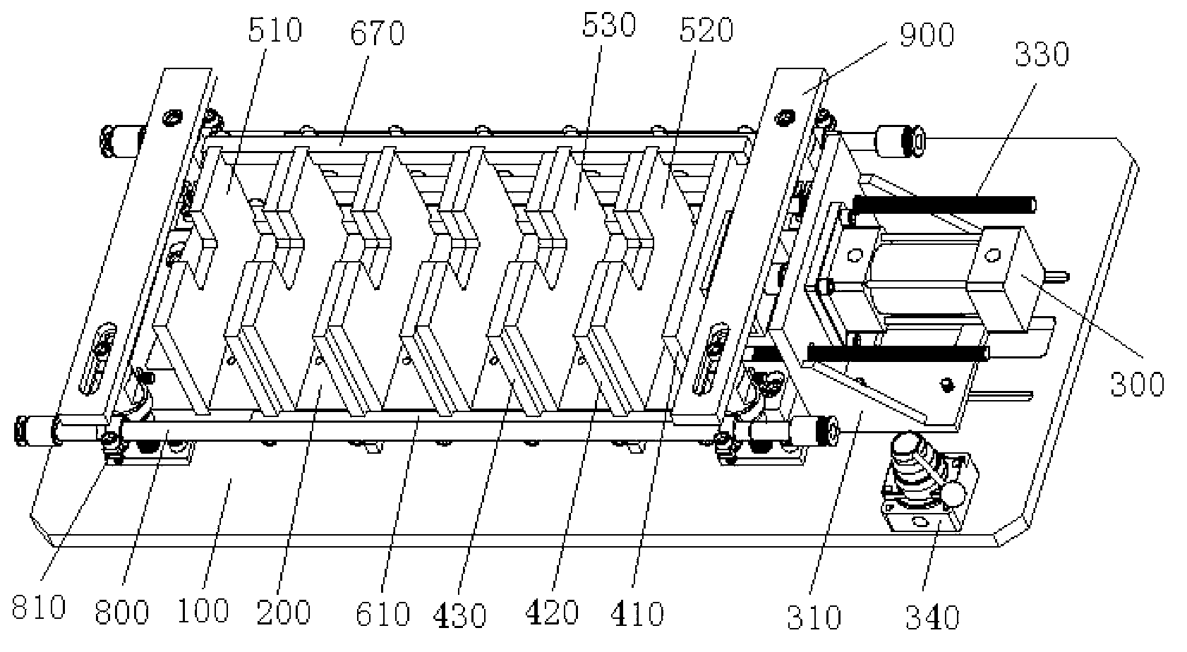
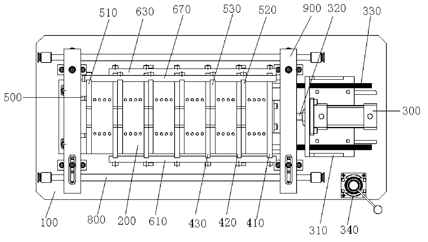
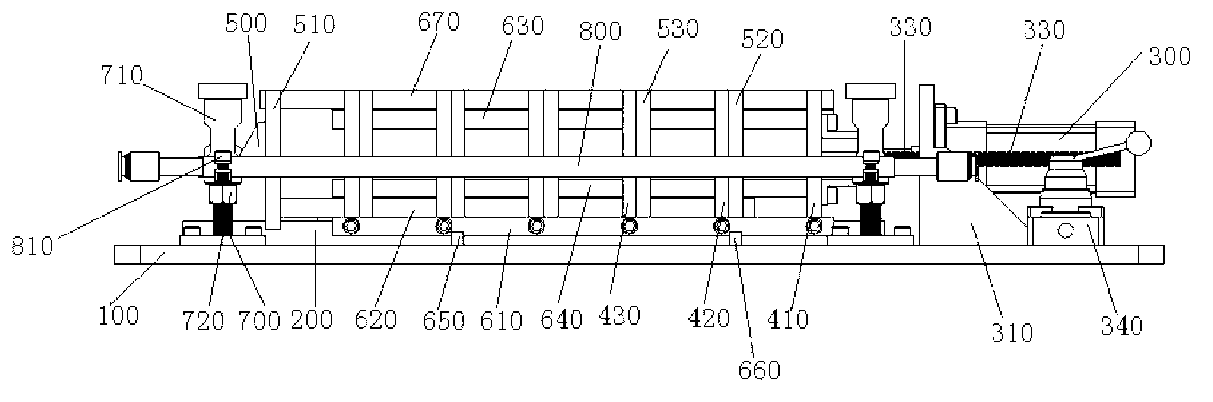
[0031] Please refer to figure 1 , figure 2 , the battery pole group welding device of the present application is suitable for the welding work of gravity casting pole plates and stretched mesh pole plates, including base 100 battery pole group clamping mechanism, pneumatic pressing mechanism, mold box bottom plate 200 , support column 700 and blowing mechanism, etc., the pneumatic compression mechanism, mold box bottom plate 200 and support column 700 are arranged on the base 100, the battery pole group clamping mechanism is set on the mold box bottom plate 200, and the battery pole group clamping mechanism includes The movable side plate group and the fixed side plate group, the movable side plate group comprises the first movable side plate 410 and the second movable side plate 420, the fixed side plate group comprises the first fixed side plate 510 and the second fixed side plate 520, the first The movable side plate 410 is connected with the pneumatic pressing mechanism ...

Embodiment 2

[0040] A battery electrode group welding method, using the battery electrode group welding device in Embodiment 1 to weld the battery electrode group, comprising the following steps:

[0041] After the battery electrode group and the separator are made into a battery electrode group, put it into the battery electrode group welding device, and start the pneumatic pressing device to compress the electrode group;

[0042] Put the comb plate on the battery pole group, insert the tabs of the pole group into the comb plate, press the bead, put the welding parts and poles, and then weld the battery pole group;

[0043] After the welding is completed, clean the lead slag and ash on the comb board, remove the bead, lightly tap the lower comb board with a rubber hammer and other tools, loosen the pneumatic pressing device to retract the movable side plate, and take out the battery electrode that has been soldered. Group into the battery case. Clean up the lead ash and lead slag in the ...


PUM


Abstract

The invention discloses a battery pole group welding device. The battery pole group welding device comprises a base, a battery pole group clamping mechanism and a pneumatic compressing mechanism, wherein the battery pole group clamping mechanism and the pneumatic compressing mechanism are in driving connection. The battery pole group welding device further comprises a mold box base plate which is arranged on the base, wherein the battery pole group clamping mechanism is arranged on the mold box base plate and comprises a movable side plate group and a fixed side plate group. The invention further discloses a battery pole group welding method. According to the device and the method, a first movable side plate, a second movable side plate, a first fixed side plate and a second fixed side plate which are connected with the pneumatic compressing mechanism are arranged, the first movable side plate is pushed by the pneumatic compressing mechanism, the second movable side plate is driven by the first movable side plate through a first connecting rod, and battery poles and separation plates, which are placed between the movable side plate group and the fixed side plate group are simultaneously compressed, so that the aim that whole groups of battery poles are welded together can be realized.

Description

technical field [0001] The present application relates to the field of battery production equipment, in particular to a battery electrode group welding device and welding method. Background technique [0002] In the prior art, the general process for welding battery pole groups is as follows: weld butt weldments, poles, etc. on a single pole group, and then combine multiple pole groups. Separators are added between the groups, and finally the entire battery electrode group is packed into the battery case. This process is cumbersome, consumes a lot of labor, and the production efficiency is low. In addition, the separator is easily pierced by the pole plate when the battery pole group is assembled, which greatly increases the probability of short circuit of the pole group and increases the failure rate of the product. Contents of the invention [0003] The technical problem to be solved in this application is to provide a battery electrode group welding device and welding ...

Claims


Application Information

Patent Timeline
IPC IPC(8): B23K5/22B23K37/04H01M10/14
CPCY02E60/126Y02E60/10Y02P70/50
Inventor 彭小勐刘浩
Owner ZHAOQING LEOCH BATTERY TECH
Why Eureka
Try Eureka