Oil-water separating device for separation and recovery of thin oil film

An oil-water separation device, separation and recovery technology, which can be used in oil/oily substance/float removal devices, liquid separation, separation methods, etc.

Active Publication Date: 2013-05-01
SHANDONG HUATE MAGNET TECH +1
View PDF6 Cites 11 Cited by
  • Summary
  • Abstract
  • Description
  • Claims
  • Application Information

AI Technical Summary

Problems solved by technology

Therefore, the recovery and separat...

Method used


Image

  • Oil-water separating device for separation and recovery of thin oil film
  • Oil-water separating device for separation and recovery of thin oil film
  • Oil-water separating device for separation and recovery of thin oil film

Examples


Embodiment 1

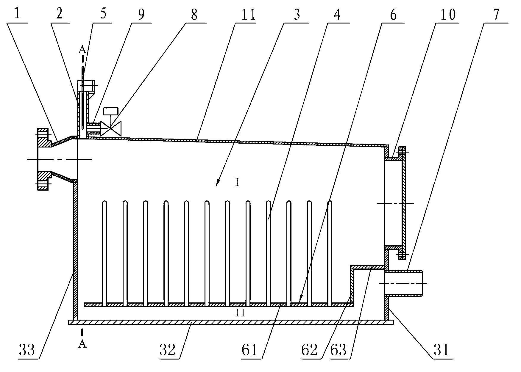
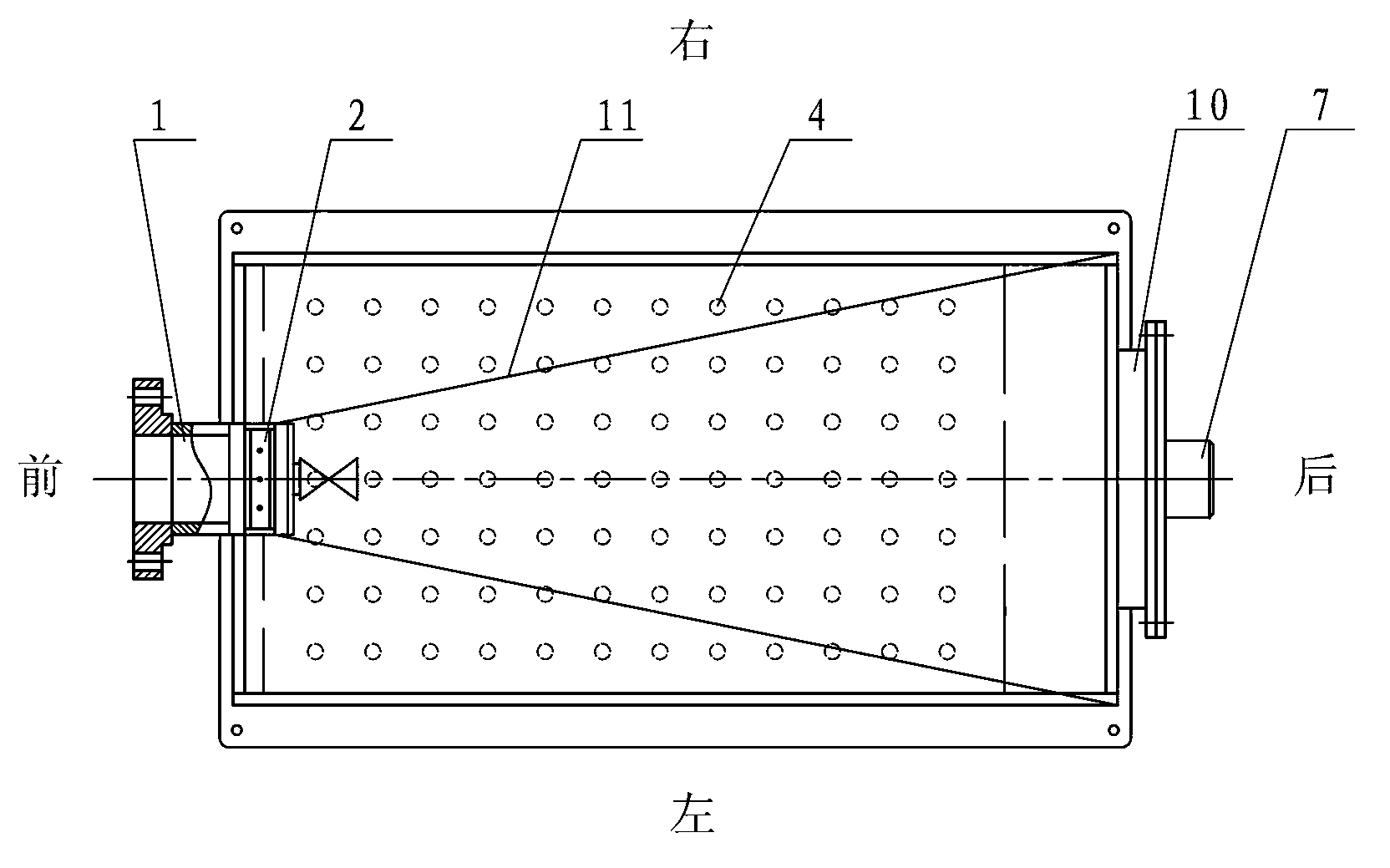
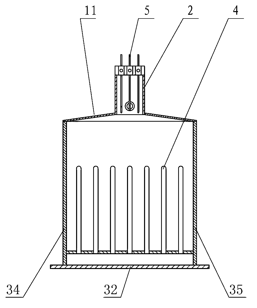
[0025] Such as figure 1 , figure 2 and image 3 Commonly shown is an oil-water separation device for thin oil film separation and recovery according to Embodiment 1 of the present invention, wherein the front, back, left and right directions are defined according to figure 2 As shown, the oil-water separation device of the present embodiment comprises:

[0026] Casing 3, this casing 3 is surrounded by bottom panel 32, front panel 33, rear panel 31, left panel 35 and right panel 34 jointly, and casing 3 is the cuboid shape of top opening; There is an inlet 1, an outlet 7 is provided at the lower part of the outer wall of the rear panel 31, and a layer of flow blocking device is provided at the lower part of the box body 3. The flow blocking device includes a horizontally arranged flow blocking separation plate 6, and the flow blocking separation plate 6 There are several columns perpendicular to it densely and uniformly distributed on it, and several columns form a square ...

Embodiment 2

[0035] Such as Figure 5 and Figure 6 As shown together, it is an oil-water separation device for thin oil film separation and recovery in Embodiment 2 of the present invention. Embodiment 2 is basically the same as Embodiment 1, except that the flow blocking device is provided with two layers up and down, from bottom to top number, there is a front gap between the flow-blocking separation plate 6 of the first layer and the front panel 33 of the box body 3, and between the flow-blocking separation plate 6 of the second layer and the rear panel 31 of the box body 3 The rear gap is left, and the upper and lower layers of flow-blocking separation plates divide the interior of the box body 3 into connected upper space I, middle space III and lower space II. Decrease can prolong the residence time of the fluid in the tank, make the oil fully float, and further improve the effect of oil-water separation.

[0036] Of course, the flow blocking device is not limited to one or two la...


PUM


Abstract

The invention discloses an oil-water separating device for separation and recovery of a thin oil film. The oil-water separating device comprises a tank body, a tank cover and an oil collecting well, wherein an inlet is formed in front of the tank body, an outlet is formed in the rear part of the tank body, and at least one layer of choked flow device consisting of a choked flow separating plate and a comb column array is arranged at the lower part in the tank body; the tank cover which gradually rises from rear to front and from left and right to middle to form a conical structure is connected to the upper side of the tank body in a sealing manner; and the oil collecting well is vertically arranged at the highest part of the conical structure on the outer wall of the tank cover, the oil collecting well is respectively communicated with the inside of the tank body and external atmosphere, an oil-level detector is arranged in the oil collecting well, a connecting side pipe is arranged on the pipe wall of the oil collecting well, and an electromagnetic valve is arranged on the connecting side pipe. The oil-water separating device disclosed by the invention is in a structure of bilateral symmetry with regard to the central line of the tank body. The oil-water separating device for separation and recovery of the thin oil film is especially suitable for oil-water separation and recovery of a micron-order thin oil film.

Description

technical field [0001] The invention relates to the technical field of oil-water separation equipment, in particular to an oil-water separation device for thin oil film separation and recovery. Background technique [0002] In recent years, marine oil spills and oil pollution accidents have occurred frequently, which has had a great impact on the marine environment. Oily sewage usually exists in the form of oil-water stratified flow. The oil floats on the water surface, forming a thin oil film, or even oil blooms. For example, in June 2011, the Penglai 19-3 oil field in Bohai Sea leaked, and an oil film appeared on the nearby sea surface. For this kind of oily sewage with a thin oil layer, it is usually surrounded and not collected, or sprayed with a chemical dispersant to make the oil slick gather into small balls, sink 4 to 5 meters below the water surface or sea surface, and let it drift or naturally Degradation; Because chemical dispersants can cause secondary pollution...

Claims


Application Information

Patent Timeline
IPC IPC(8): C02F1/40
Inventor 李建王兆连彭燕陈雷赵凌志刘风亮沙次文刘世昌贾洪利
Owner SHANDONG HUATE MAGNET TECH
Why Eureka
Try Eureka