AOI (automated optical inspection) device with multiple area-array cameras and image shooting method thereof

An area array camera and equipment technology, applied in the direction of measuring devices, material analysis through optical means, instruments, etc., can solve the problem that AOI equipment is difficult to meet the speed requirements, increase the complexity and cost of the system, and enlarge the field of view of the area array camera, etc. Problems, to achieve the effect of reducing the time of camera shooting, taking pictures and scanning quickly, and reducing the time of camera movement

Inactive Publication Date: 2013-05-01
王锦峰
View PDF4 Cites 31 Cited by
  • Summary
  • Abstract
  • Description
  • Claims
  • Application Information

AI Technical Summary

Problems solved by technology

[0004] In the production line that requires high detection speed, traditional AOI equipment is difficult to meet the speed requirements, and there is a problem of low detection efficiency
The test time can be reduced by reducing the number of motor movements and camera shots. The traditional method is to use high-resolution area array cameras or line array cameras. However, high-resolution cameras are expensive, and the field of view of area array cameras becomes larger. It also leads to the problem of serious image distortion. The line scan camera takes a long time to acquire images, and a feedback link is required, which increases the complexity and cost of the system.

Method used


Image

  • AOI (automated optical inspection) device with multiple area-array cameras and image shooting method thereof
  • AOI (automated optical inspection) device with multiple area-array cameras and image shooting method thereof
  • AOI (automated optical inspection) device with multiple area-array cameras and image shooting method thereof

Examples


Embodiment

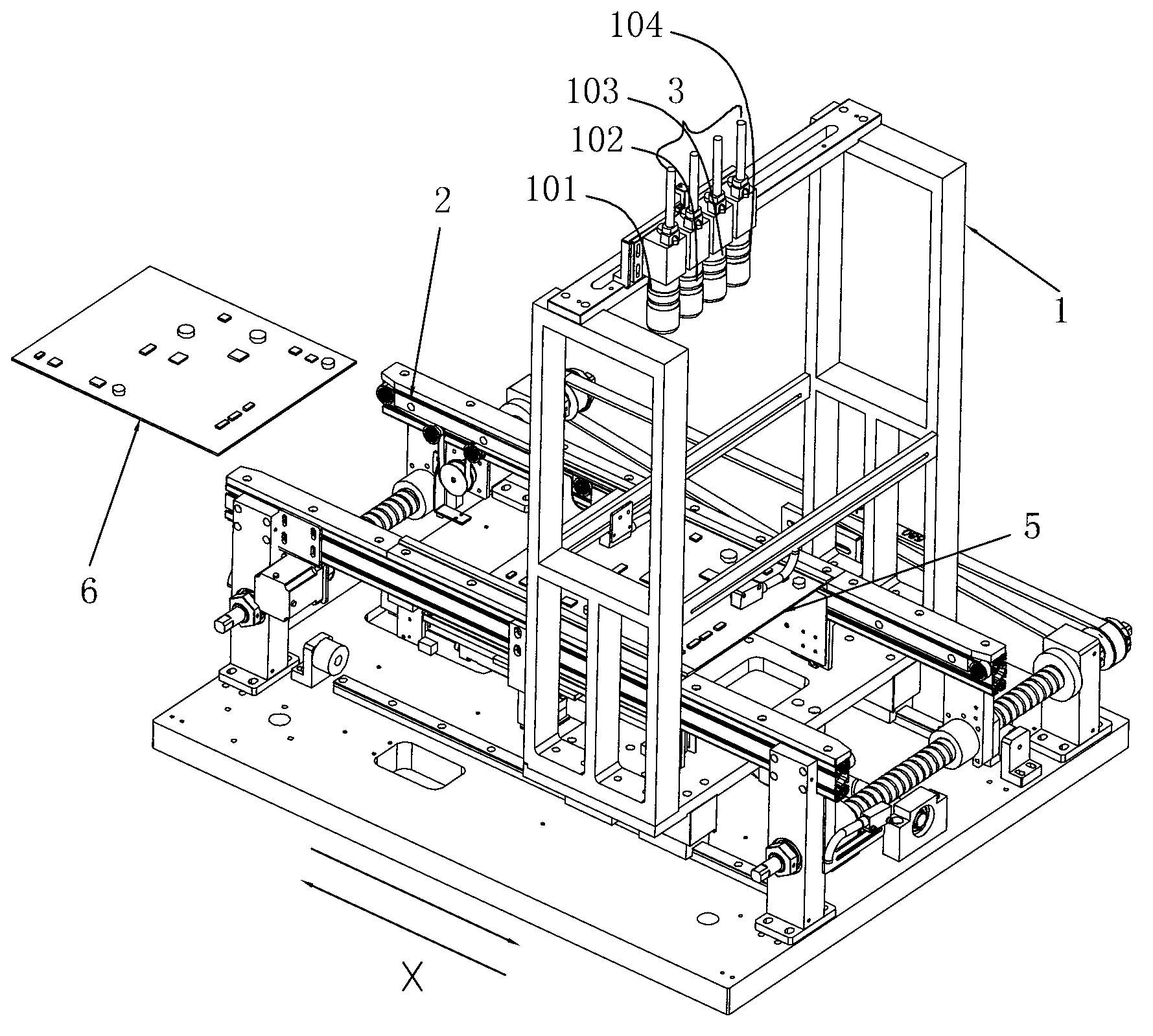
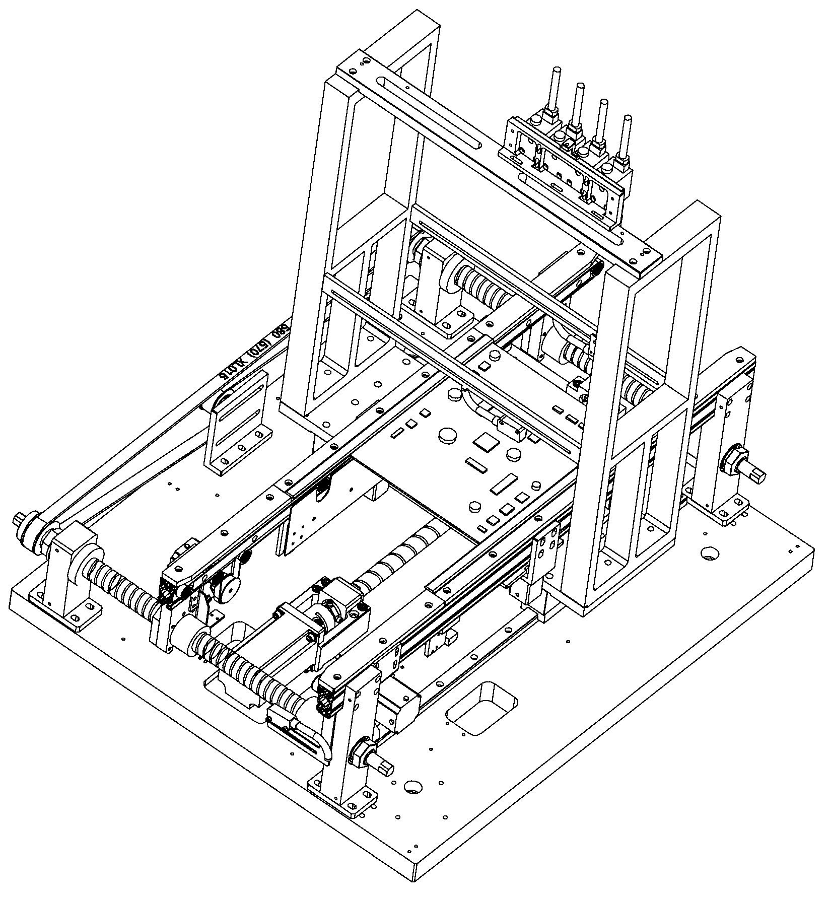
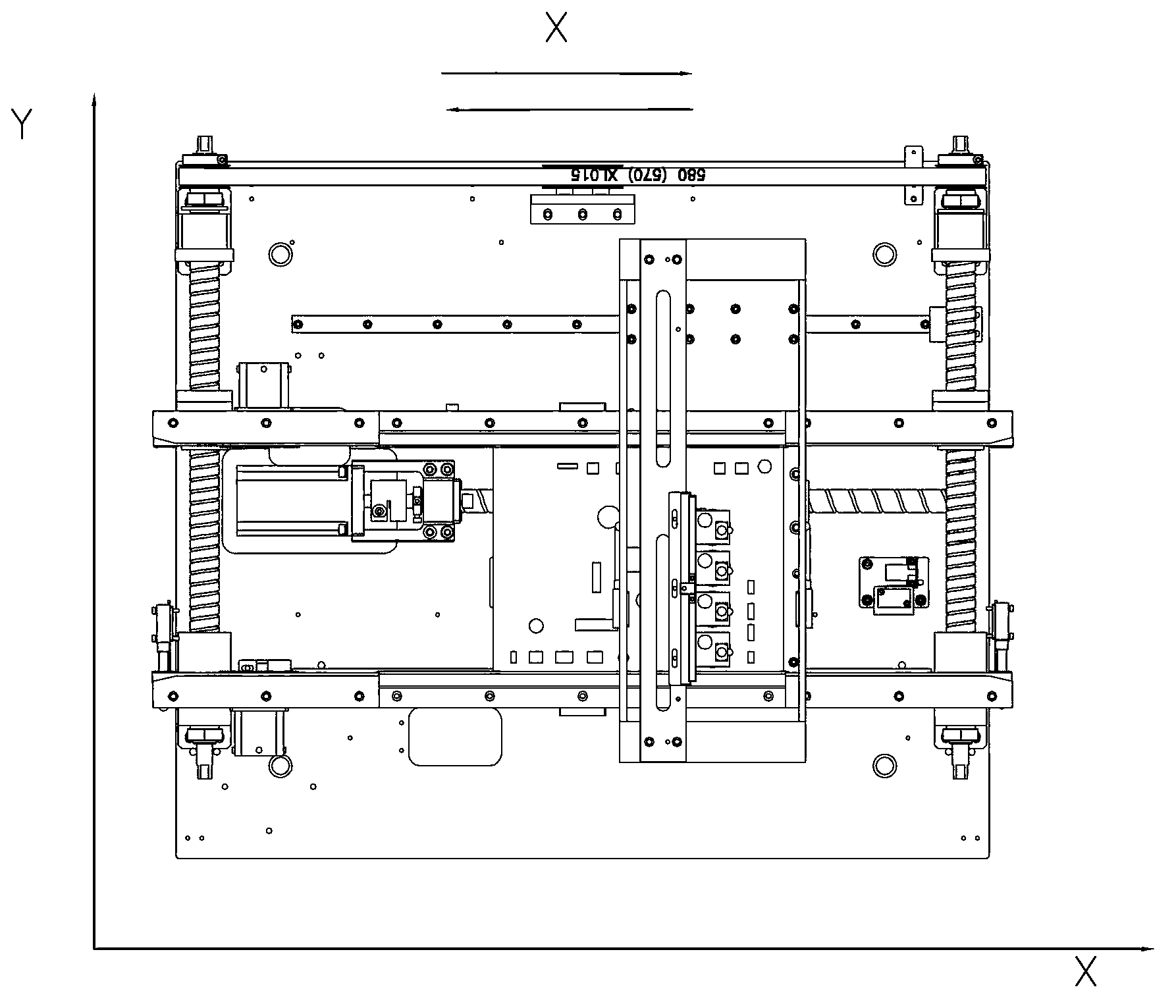
[0030] Example: such as figure 1 , figure 2 , image 3 , Figure 4 , Figure 5 As shown, the multi-array camera AOI equipment includes a camera frame 1 that can move in the X-axis direction of the equipment, and a transmission mechanism 2 that transmits PCB boards to the stage. The track direction of the transmission mechanism is taken as the X-axis direction of the equipment. Described camera frame 1 is provided with camera array, and camera array 3 is made of at least two area array cameras, and the shooting direction of each area array camera is in the same direction, and the FOV of adjacent two area array cameras has overlapping area 4 (as overlapping 1-5mm) , also includes a controller that controls each area array camera to take images of the PCB board at the same time, and a processor that stitches the images captured by each camera into one image. The processor can be a computer device or a single-chip microcomputer or other conventional image processing device. ...


PUM


Abstract

The invention discloses an AOI device with multiple area-array cameras. The AOI device comprises a camera frame capable of moving in the X axis of the device, and a conveying mechanism for conveying PCBs (printed circuit boards) for a working stage, wherein the camera frame is provided with a camera array formed by at least two area-array cameras; the shooting directions of each area-array camera is the same; FOV (fields of view) of two adjacent area-array cameras are provided with overlapping regions; and the device further comprises a controller used for controlling each area-array camera to shoot images of a PCB simultaneously, and a processor used for splicing the images shot by each camera into one image. The AOI device enables the images shot by a plurality of cameras to be spliced into a complete image through arranging the plurality of area-array cameras side by side in the Y axis. The invention further discloses an image shooting method of the device. Compared with the prior art, motor moving time and camera moving time are reduced, and the scanning speed for shooting is high, so that the efficiency of the AOI device is improved remarkably, and time and cost are saved.

Description

technical field [0001] The invention relates to an AOI device for a multi-array camera, belongs to the technical field of the AOI device for a multi-array camera, and also relates to an image shooting method of the device. Background technique [0002] In the SMT patch mounting production line, AOI equipment is used to inspect the quality of solder paste and electronic components on the PCB, which can reduce the defect rate of electronic products and reduce production costs. [0003] Traditional AOI equipment uses an area array or line array camera to inspect the PCB board; due to the limitation of the field of view of the area array camera, it is necessary to use the motor to move the camera in the X-Y direction to take pictures of the PCB board many times. [0004] In the production line that requires high detection speed, traditional AOI equipment is difficult to meet the speed requirements, and there is a problem of low detection efficiency. The test time can be reduced...

Claims


Application Information

Patent Timeline
Patent Type & Authority Applications(China)
IPC IPC(8): G01N21/84G01B11/00
Inventor 王锦峰
Owner 王锦峰
Why Eureka
Try Eureka