

Operating temperature self-adjusting system of high repetition frequency industrial excimer laser
An excimer laser, working temperature technology, used in lasers, phonon exciters, laser parts and other directions, can solve the problem of output characteristics changing with working temperature, and achieve the effect of reducing equipment damage and improving laser output power
- Summary
- Abstract
- Description
- Claims
- Application Information
AI Technical Summary
Problems solved by technology
Method used
Image

Examples
Embodiment Construction
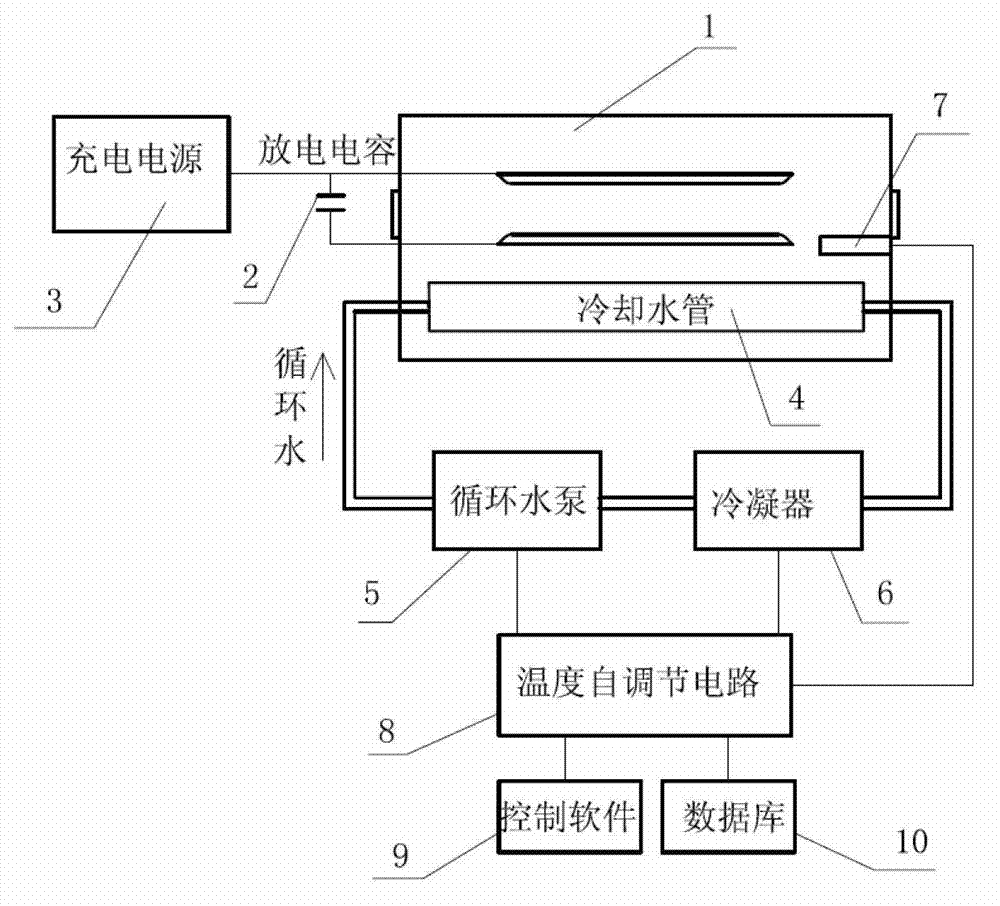
[0020] Such as figure 1 shown. A high repetition frequency industrial excimer laser working temperature self-regulation system, including a laser discharge cavity 1, a pair of discharge electrodes 14, a cooling water pipe 4, and a temperature sensor 7 are arranged in the laser discharge cavity 1, and a capacitor is connected between the two discharge electrodes 14 2, and the capacitor 2 is connected to the external charging power supply 3 through wires, the cooling water pipe 4 is connected to a circulating water pump 5 and a condenser 6 through the pipeline to form a circulating cooling water circuit, and also includes a temperature self-regulating circuit 8, a temperature sensor 7, a circulating The water pump 5 and the condenser 6 are respectively connected to a temperature self-regulating circuit 8 .
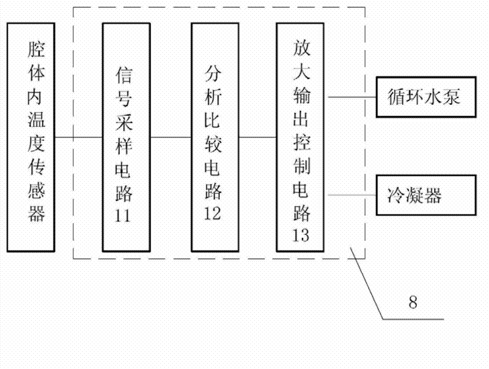
[0021] Such as figure 2 shown. The temperature self-regulating circuit 8 is composed of an analysis and comparison circuit 12 , a signal sampling circuit 11 connected to...
PUM
 Abstract
Description
Claims
Application Information