

Single-lamp single-rod double-cavity light path system for laser cutting machine
An optical path system, cavity laser technology, applied in laser welding equipment, welding equipment, metal processing equipment and other directions, can solve the problems of limited cutting plate thickness, low laser output power, low light energy efficiency, etc., to solve cutting problems, improve Laser output power, the effect of improving cutting ability
- Summary
- Abstract
- Description
- Claims
- Application Information
AI Technical Summary
Problems solved by technology
Method used
Image

Examples
Embodiment Construction
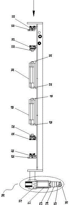
[0014] Such as figure 1 As mentioned above, a single-lamp single-rod double-cavity laser cutting machine optical path system is provided. The direction indicated by the arrow on the right side of the figure is the beam transmission direction. Along the beam transmission direction, a red light indicator 11, a full mirror 21, The first gold cavity 30, the second gold cavity 40, the half mirror 51, the water-cooled beam expander 61 and the follow-up cutting head 70, wherein the red light indicator 11 is installed on the four-dimensional mirror frame 12; the full mirror 21 is installed on the water-cooled On the two-dimensional mirror frame 22; the half mirror 51 is installed on the water-cooled two-dimensional mirror frame 52; the water-cooled beam expander 61 is installed on the four-dimensional mirror frame 62; the right end of the first gold chamber 30 is provided with the first xenon lamp 31, the left end is provided There is a first yttrium aluminum garnet crystal rod 32; th...
PUM
 Abstract
Description
Claims
Application Information