Supercharge Your Innovation With Domain-Expert AI Agents!

Passive power factor correction power supply circuit

A passive power factor and power circuit technology, applied in the direction of high-efficiency power electronic conversion, output power conversion devices, electrical components, etc., can solve the problems of filter capacitor withstand voltage and high performance requirements, high failure rate, low reliability, etc. , to achieve the effect of reducing harmonic components, easy to use, and high reliability

Inactive Publication Date: 2013-05-01
TIANJIN RAILWAY SIGNAL
View PDF2 Cites 4 Cited by
  • Summary
  • Abstract
  • Description
  • Claims
  • Application Information

AI Technical Summary

Problems solved by technology

Because the active power factor correction DC bus voltage is high, the filter capacitor working on the DC bus has high withstand voltage and performance requirements; at the same time, in the DC / DC conversion circuit of the subsequent stage, the voltage stress of the power device is also large, especially When the power factor correction is out of control, a high voltage will be formed on the DC bus, which will directly cause the filter capacitor on the DC bus and the power device in the DC / DC conversion circuit to be broken down and fail.
From the analysis of the failure causes of this type of power supply in recent years, the failure rate of the active power factor correction (PFC) part is relatively high, resulting in a decrease in the reliability of this power supply. There is a railway DC switching power supply due to the active power factor correction circuit faults, technical problems that lead to its low reliability

Method used


Image

  • Passive power factor correction power supply circuit
  • Passive power factor correction power supply circuit
  • Passive power factor correction power supply circuit

Examples


Embodiment Construction

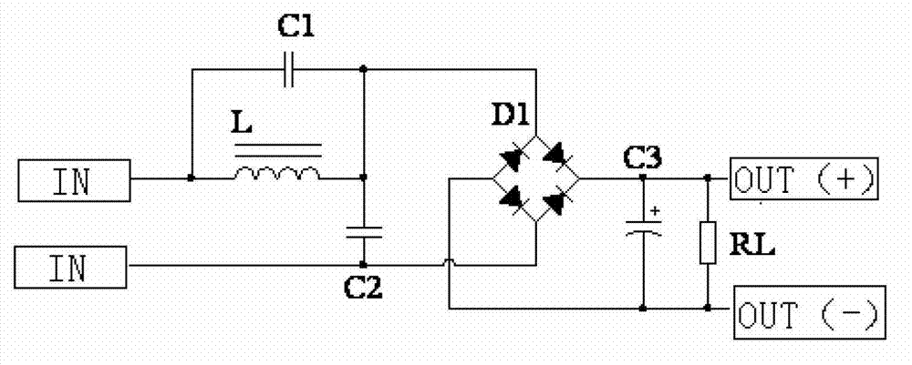
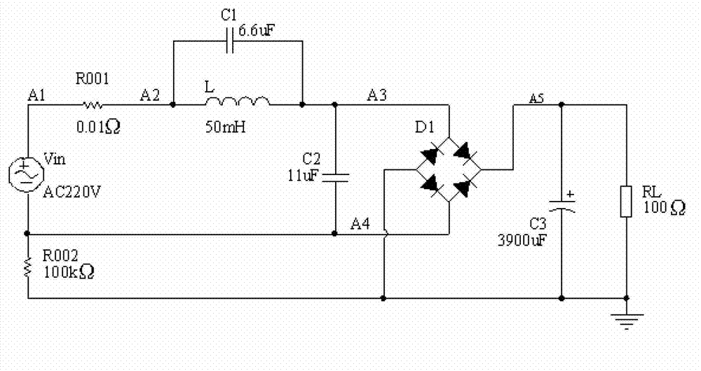
[0012] Such as Figure 1 to 3 As shown, a passive power factor correction power supply circuit of the present invention includes an AC power supply, a correction inductor L, a correction capacitor C2, a correction capacitor C1, a filter capacitor C3, a resistor RL, and a full-bridge rectifier circuit D1. The correction inductor L and the correction capacitor C2 are connected in series to form a loop, both ends of the correction inductor L are connected in parallel with the correction capacitor C1, both ends of the correction capacitor C2 are connected in parallel with the input end of the full-bridge rectifier circuit D1, The output terminals of the full-bridge rectifier circuit D1 are respectively connected in parallel with the filter capacitor C3 and the resistor RL, and both ends of the filter capacitor C3 are output terminals. The correction capacitor C1 is 6.6 uf, the correction capacitor C2 is 11 uf, the filter capacitor C3 is 3900 uf, the correction inductance L is 50 mH...


PUM

PropertyMeasurementUnit
Filter capacitoraaaaaaaaaa
Resistanceaaaaaaaaaa

Abstract

The invention provides a passive power factor correction power supply circuit which comprises an AC (Alternating Current) power supply, a correction inductor L, a correction capacitor C2, a correction capacitor C1, a filtration capacitor C3, a resister RL and a full bridge rectification circuit D1, wherein the AC power supply is serially connected with the correction inductor L and the correction capacitor C2 to form a loop; two ends of the correction inductor L are parrallelly connected with the correction capacitor C1; two ends of the correction capacitor C2 are parallelly connected with the input end of the full-bridge rectification circuit D1; the output end of the full-bridge rectification circuit D1 are respectively and parrallelly connected with the filtration capacitor C3 and the resister RL; and the two ends of the resister RL are output ends. The passive power factor correction power supply circuit provided by the invention has the following beneficial effects: by virtue of performing proper lectotype and optimization on the correction inductor L, the correction capacitor C1 and the correction capacitor C2, a passive power factor correction function for the input of the AC power supply is realized, and under the conditions of rated AC input and rated DC (Direct Current) load, the power factor can be up to 0.96; and the passive power factor correction power supply circuit has the advantages of simple circuit, convenience in use, high reliability of a correction circuit, and the like.

Description

Technical field [0001] The invention belongs to the field of power supply circuits, and in particular relates to a passive power factor correction power supply circuit. Background technique [0002] Most railway signal switching power supply modules require power factor correction (PFC). In the existing technology, these power supplies usually use active power factor correction. Because the active power factor correction DC bus voltage is relatively high, the filter capacitor working on the DC bus has high withstand voltage and performance requirements; at the same time, the voltage stress of the power device is also relatively large in the subsequent DC / DC conversion circuit, especially When the power factor correction is out of control, high voltage will be formed on the DC bus, which directly causes the filter capacitor on the DC bus and the power devices in the DC / DC conversion circuit to be broken down. From the analysis of the failure causes of this type of power supply in...

Claims


Application Information

Patent Timeline
IPC IPC(8): H02M1/42
CPCY02B70/123Y02B70/10
Inventor 张玉喜姜海峡成会芳鞠宏伟
Owner TIANJIN RAILWAY SIGNAL
Features
  • R&D
  • Intellectual Property
  • Life Sciences
  • Materials
  • Tech Scout
  • Unparalleled Data Quality
  • Higher Quality Content
  • 60% Fewer Hallucinations
Learn More