Digital power factor converter with fast transient response function and control method of digital power factor converter

A digital power and transient response technology, applied in the direction of AC power input conversion to DC power output, output power conversion device, sustainable manufacturing/processing, etc., can solve the problem of transient response performance of digital power factor correction converters, etc. problem, to achieve scalability and portability, reduce control hysteresis, and reduce energy loss

Inactive Publication Date: 2013-05-01
SOUTHEAST UNIV
View PDF5 Cites 28 Cited by
  • Summary
  • Abstract
  • Description
  • Claims
  • Application Information

AI Technical Summary

Problems solved by technology

Moreover, there are steps such as data sampling, quantization, data processing, algorithm compensation, and DPWM generation in the control loop of the digital converter. The

Method used


Image

  • Digital power factor converter with fast transient response function and control method of digital power factor converter
  • Digital power factor converter with fast transient response function and control method of digital power factor converter
  • Digital power factor converter with fast transient response function and control method of digital power factor converter

Examples


Embodiment Construction

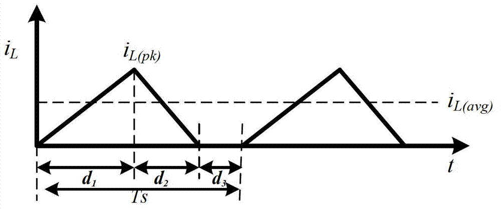
[0027] figure 1 Shown is the inductor current waveform of the DCM mode (Discontinuous Current Mode) power factor correction converter. During the conduction period of the switch tube, the voltage value at both ends of the inductor is V in , the inductor current is The linear rising slope rises from zero current to iL(pk) , the rise time is d 1 T s , when the switch tube is turned off, the voltage across the inductor is V in -V o , the inductor current is The linear descending slope is given by i L(pk) Falling to zero current, the fall time is d 2 T s , at d 3 T s During the time period, the inductor current is kept at a zero current state.

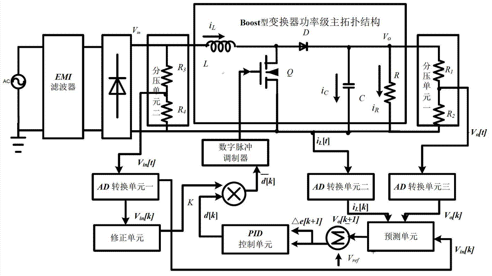
[0028] The overall diagram of the digital power factor converter with high power factor and fast transient response of the present invention is as follows figure 2 As shown, it includes EMI filter, diode rectifier circuit, Boost converter power stage main topology, first and second voltage dividing units, first, second and th...


PUM


Abstract

The invention relates to a digital power factor converter with a fast transient response function. The digital power factor converter is provided with an EMI (electro magnetic interference) filter, a rectifying circuit, a Boost type converter power stage main topology structure, two voltage dividing units, three A/D (analog to digital) sampling converting units, a prediction control unit, a PID (proportion integration differentiation) control unit, a duty ratio correction unit and a digital pulse modulator, wherein the alternating current voltage AC is connected with the input end of the EMI filter, the output end of the EMI filter is connected with the input end of the rectifying circuit, the input end of the second voltage dividing unit is connected with the output end of the rectifying circuit, i.e. the input end of the main topology structure, the input end of the first voltage dividing unit is connected with the output end of the main topology, the output ends of the three A/D sampling converting units are respectively connected with the prediction control unit, after output signals and reference voltage signals Vref are compared, voltage error signals and voltage error deviation signals are output to the PID control unit, output signals of the duty ratio correction unit and output signals of the PID control unit are multiplied and are then connected with the digital pulse modulator, and the output end of the digital pulse modulator is connected with a grid electrode of an MOS (metal oxide semiconductor) transistor Q in the main topology structure.

Description

technical field [0001] The present invention relates to a digital power factor converter, in particular to a fast transient response digital power factor converter and its control method, the converter can effectively improve the power factor value close to 1, and can overcome the time delay of the digital converter effect to improve the transient response performance of the converter. Background technique [0002] Power electronic devices such as switching converters have been widely used in power systems, industries, transportation, and households. The resulting problems of grid-side input power factor reduction and harmonic pollution are becoming more and more serious. In order to reduce harmonic pollution, ensure the power supply quality of the grid, improve the power factor at the input end of the switching converter, and achieve the effect of saving energy, it is necessary to perform power factor correction on the power electronic device of the switching converter. Co...

Claims


Application Information

Patent Timeline
IPC IPC(8): H02M7/217H02M1/42
CPCY02B70/126Y02B70/10Y02P80/10
Inventor 孙伟锋孙大鹰程松林宋慧滨王青徐申陆生礼时龙兴
Owner SOUTHEAST UNIV
Why Eureka
Try Eureka