Electric heating catalyst

An electric heating and catalyst technology, which is applied in the direction of electric heating devices, electrical components, chemical instruments and methods, etc., can solve the problems of short circuit between electrodes and shells, reduction of insulation resistance between electrodes and shells, etc., and achieve the effect of suppressing short circuits

Inactive Publication Date: 2013-05-01
TOYOTA JIDOSHA KK
View PDF3 Cites 3 Cited by
  • Summary
  • Abstract
  • Description
  • Claims
  • Application Information

AI Technical Summary

Problems solved by technology

[0008] When condensed water exists in the electrode chamber, there is a concern that the condensed water may cause a short circuit between the electrode and the case
In addition, when the humidity in the electrode chamber increases due to the generation of steam due to the evaporation of condensed water, there is also a possibility that the insulation resistance between the electrode and the case will be greatly reduced.

Method used


Image

  • Electric heating catalyst
  • Electric heating catalyst
  • Electric heating catalyst

Examples


Embodiment 1

[0034] [Outline structure of EHC]

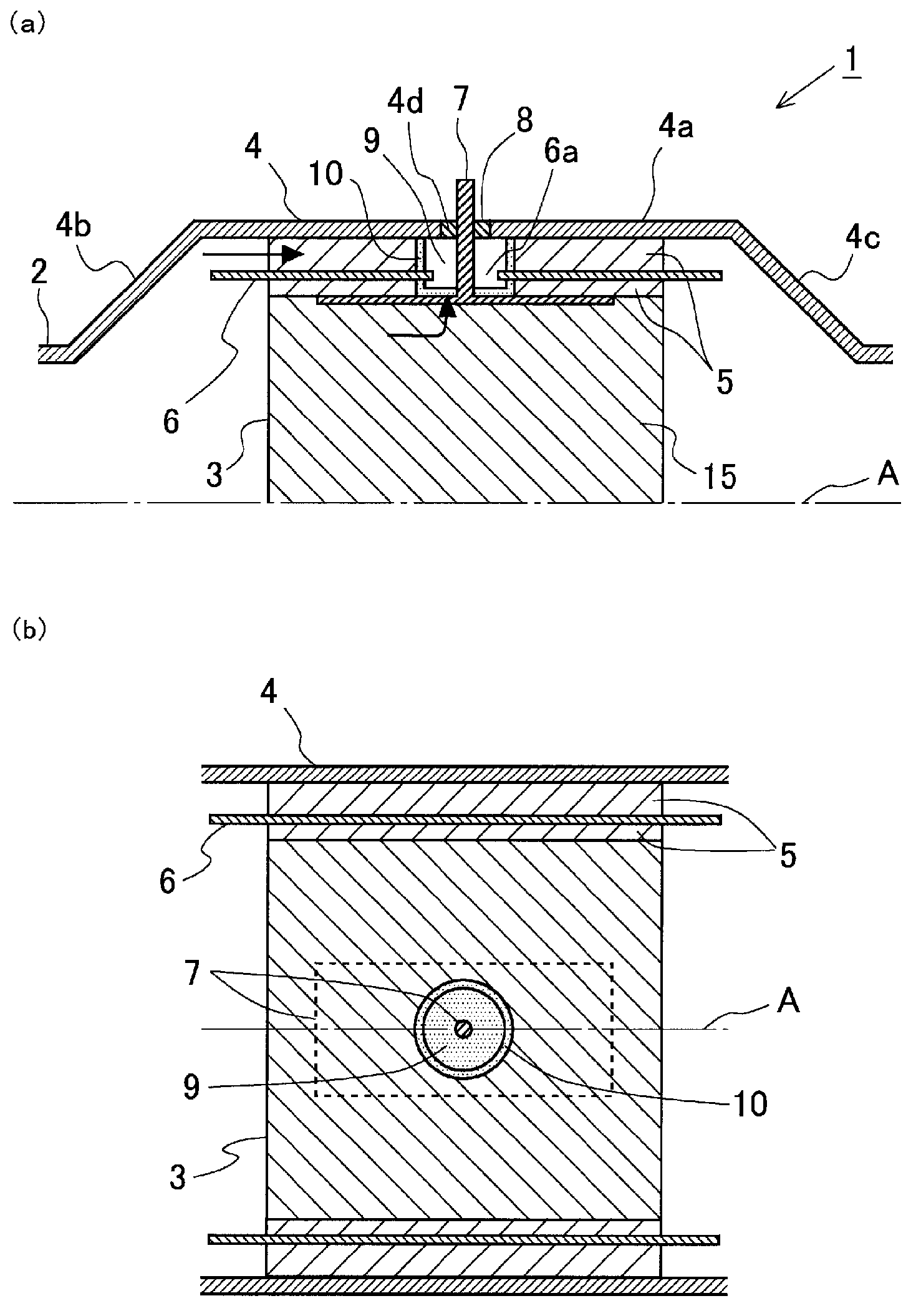
[0035] figure 1 It is a diagram showing a schematic configuration of an electrically heated catalyst (EHC) according to the present example. The EHC 1 according to the present embodiment is installed in an exhaust pipe of an internal combustion engine mounted on a vehicle. The internal combustion engine can be a diesel engine or a gasoline engine. Furthermore, the EHC 1 according to the present embodiment can also be used in a vehicle employing a hybrid system including an electric motor.

[0036] figure 1 (a) is a cross-sectional view of the EHC 1 longitudinally cut along the central axis A of the exhaust pipe 2 of the internal combustion engine. In addition, since the shape of EHC1 is line-symmetric with respect to the central axis A, therefore, in figure 1 In (a), for convenience of explanation, only the upper part of EHC1 is shown.

[0037]The EHC 1 according to this example includes a catalyst carrier 3 , a case 4 , a gasket 5 , a...

Embodiment 2

[0060] [Outline structure of EHC]

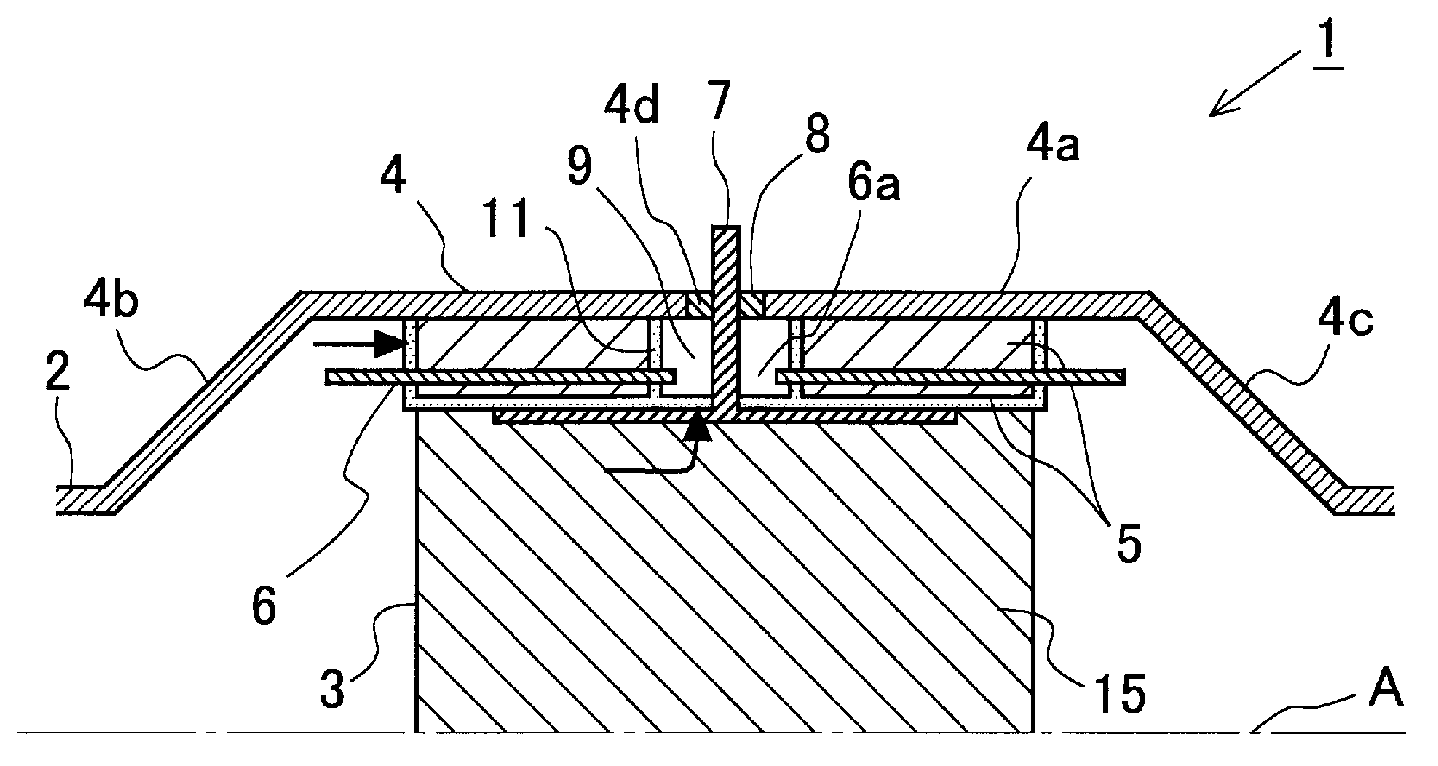
[0061] image 3 It is a diagram showing a schematic configuration of the EHC according to the present embodiment. Such as image 3 As shown, in this embodiment, in addition to the wall surface of the electrode chamber 9 , the entire outer peripheral surface of the catalyst carrier 3 and the upstream and downstream end surfaces of the mat 5 are also covered with the blocking member 11 . Like the closing member 10 according to Example 1, the closing member 11 is formed of a highly airtight insulating material that is higher in airtightness than the material forming the catalyst carrier 3 and the material forming the mat 5 and is electrically insulated. The structure other than that is the same as that of the EHC according to Example 1.

[0062] In addition, in this embodiment, the portion of the closing member 11 covering the wall surface of the electrode chamber 9 corresponds to the first closing member according to the present invention. ...

Embodiment 3

[0072] [Outline structure of EHC]

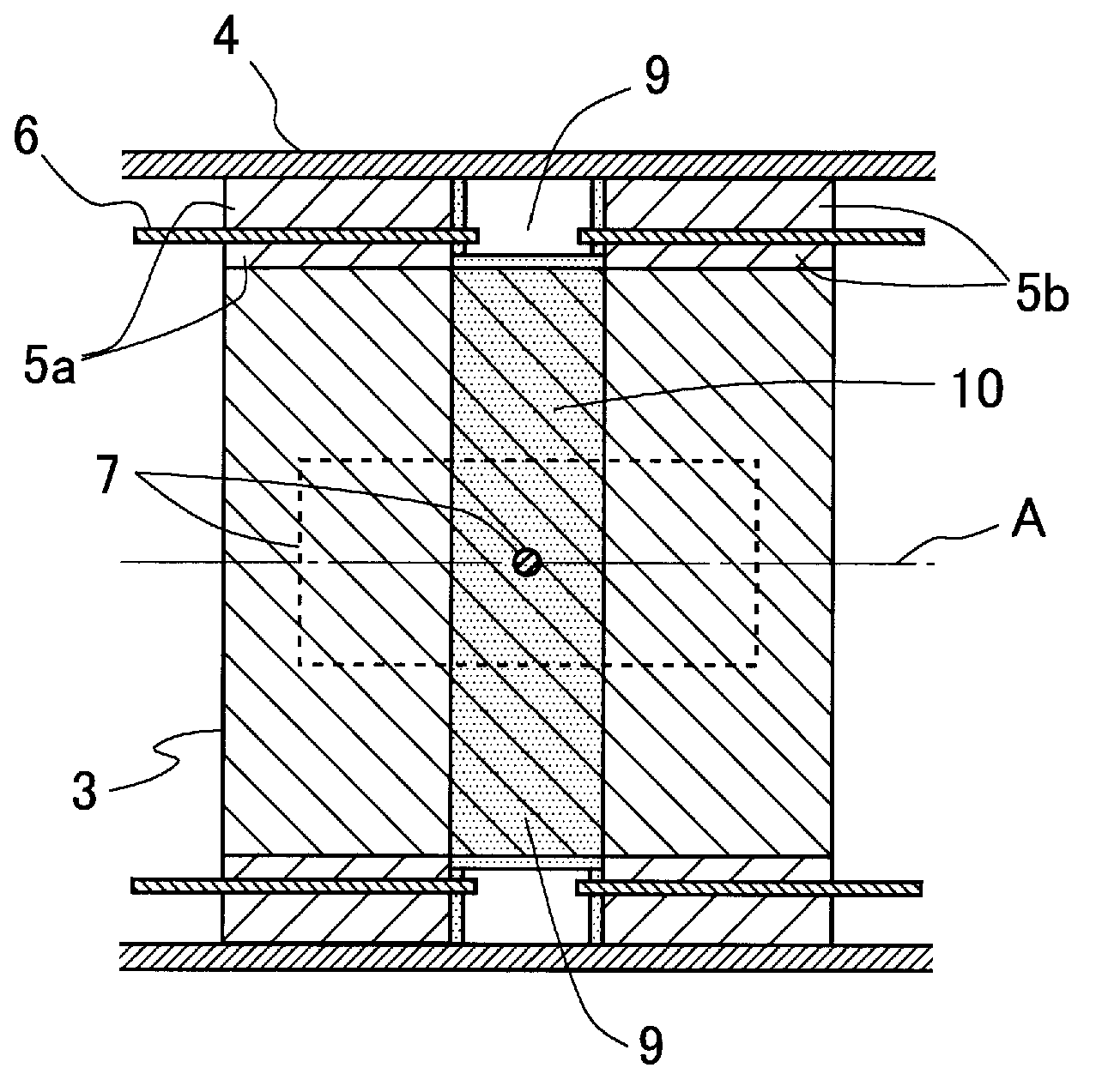
[0073] Figure 5 It is a diagram showing a schematic configuration of the EHC according to the present embodiment. Such as Figure 5 As shown, in this embodiment, the electrode chamber 9 is filled with the blocking member 12 . Like the closing member 10 according to Example 1, the closing member 11 is formed of a highly airtight insulating material that is higher in airtightness than the material forming the catalyst carrier 3 and the material forming the mat 5 and is electrically insulated. The structure other than that is the same as that of the EHC according to Example 1.

[0074] [Action and effect of the structure of the EHC related to the present embodiment]

[0075] exist Figure 5 In , arrows indicate the flow of exhaust gas and condensed water. In this embodiment, the electrode chamber 9 is closed by a highly airtight closing member 12 . Thereby, it is possible to suppress the exhaust gas and condensed water passing through t...


PUM


Abstract

The invention relates to an electric heating catalyst. The purpose of the present invention is to prevent the decrease in the insulation resistance between an electrode and a case which is usually caused by the action of condensed water in an electric heating catalyst (EHC). This EHC (1) comprises a heating element (3) which can generate heat upon the conduction of an electric power to heat a catalyst, a case (4) which accommodates the heating element, and an insulating member (5) which is arranged between the heating element (3) and the case (4) and insulates an electric power. In the case (4) of the EHC (1), an electrode chamber (9), which is a space formed around an electrode (7) that is connected to the heating element (3), is closed by a closing member (10) which has higher air-tightness than those of the heating element (3) and the insulating member (5).

Description

technical field [0001] The present invention relates to an electrically heated catalyst provided in an exhaust passage of an internal combustion engine. Background technique [0002] Conventionally, as an exhaust purification catalyst installed in an exhaust passage of an internal combustion engine, an electric heating catalyst (Electric Heating Catalyst: hereinafter referred to as EHC) in which a catalyst is heated by a heating element that generates heat by energization has been developed. [0003] In the EHC, an insulating member that insulates and insulates electricity is provided between a heat generating element that generates heat when energized and a case housing the heat generating element. For example, Patent Document 1 discloses a technique in which, in EHC, a pad of an insulator is provided between a carrier that generates heat by energization and a case housing the carrier. By providing such an insulating member, it is possible to suppress a short circuit betwe...

Claims


Application Information

Patent Timeline
Patent Type & Authority Applications(China)
IPC IPC(8): B01D53/86
CPCF01N13/14F01N13/16F01N3/2026Y02T10/26H05B1/00B01D53/86Y02T10/12
Inventor 吉冈卫熊谷典昭高木直也
Owner TOYOTA JIDOSHA KK
Why Eureka
Try Eureka