
Method of material processing by laser filamentation

A technology of laser beams and beams, applied in laser welding equipment, manufacturing tools, glass manufacturing equipment, etc., can solve the problems of not being environmentally friendly, large quantities, and increasing costs

Active Publication Date: 2013-05-01
ROFIN SINAR TECH
View PDF6 Cites 74 Cited by
  • Summary
  • Abstract
  • Description
  • Claims
  • Application Information

AI Technical Summary

Problems solved by technology

The process produces poor-quality edges, micro-cracks, wide kerf widths, and large amounts of debris, which are major drawbacks in terms of product life, quality, and reliability, and incur additional cleaning and polishing steps
The cost of deionized water to run a diamond scriber is greater than the cost of purchasing the scriber and this technique is not environmentally friendly as the water is polluted and needs to be purified which also adds to the expense
Through improved technology, the chips on the wafer have become smaller and closer to each other, which limits the diamond scribing
30um is a good scribe width, but 15um is a challenge
While the method potentially offers a fast scribing speed of 300mm / s, there are limited kerf widths, surface damage, rough cut surfaces, and ablation debris due to internally formed voids reaching the surface

Method used


Image

  • Method of material processing by laser filamentation
  • Method of material processing by laser filamentation
  • Method of material processing by laser filamentation

Examples


Embodiment

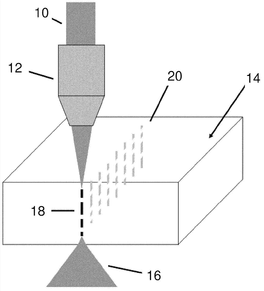
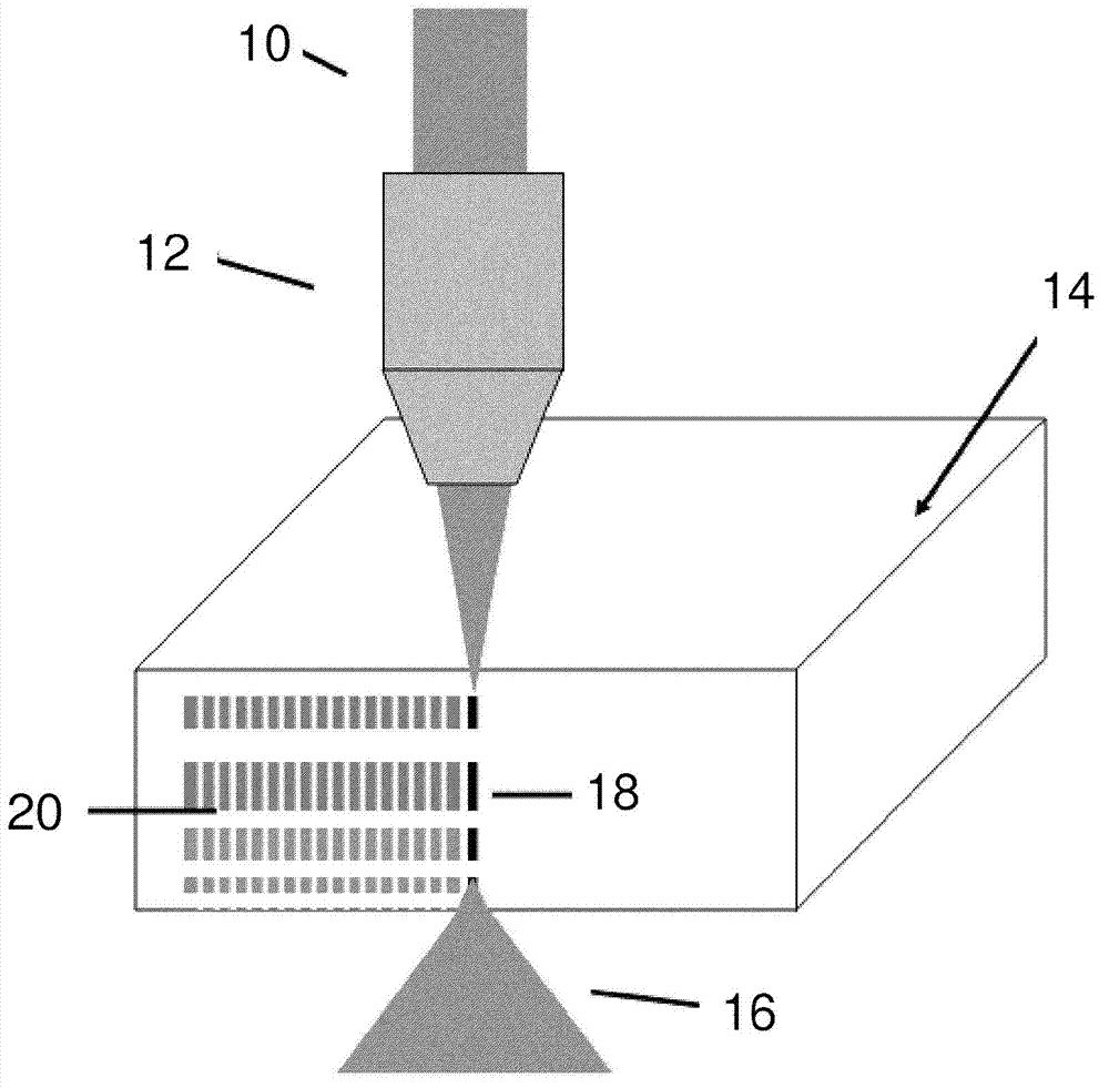
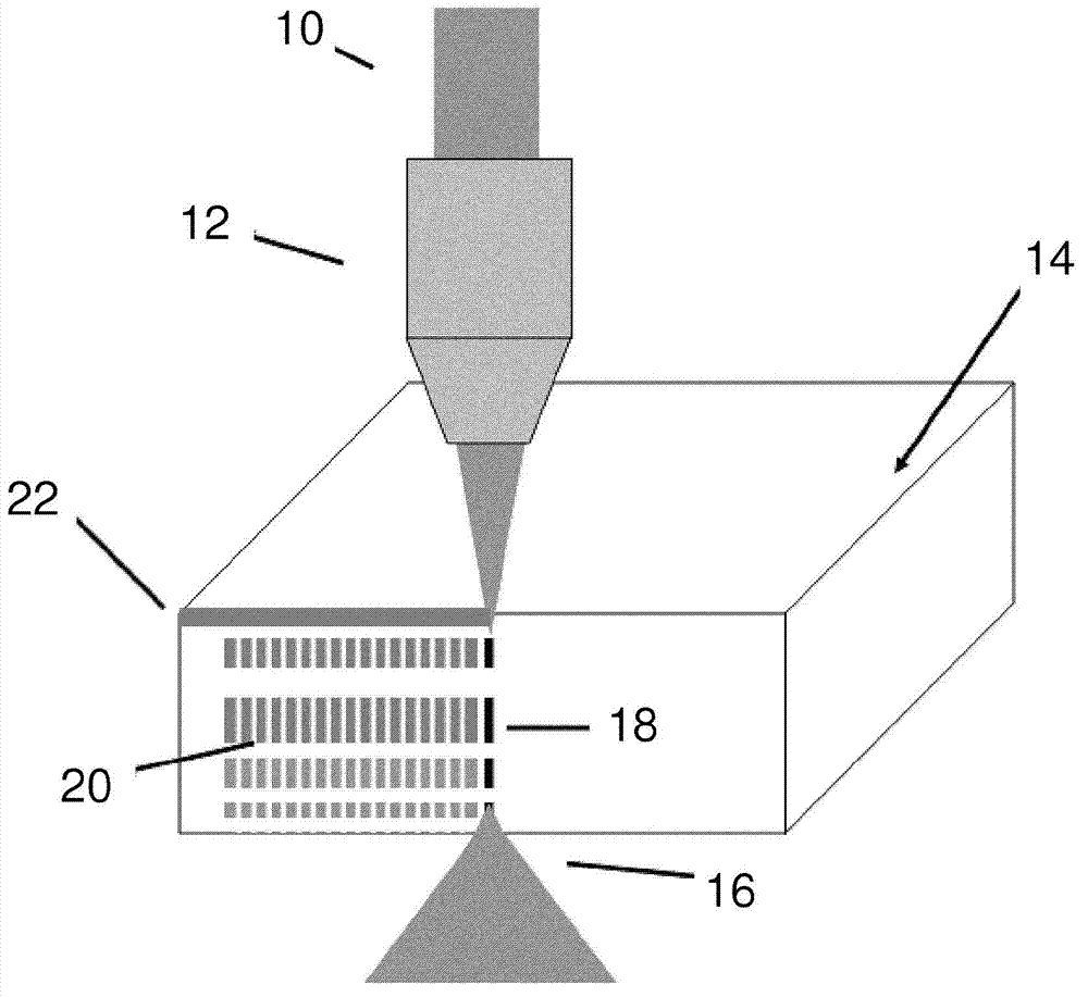
[0076] To illustrate selected embodiments, a glass plate was laser processed using a pulsed laser system producing 100 fs pulses at a repetition rate of 38 MHz with an effective wavelength of approximately 800 nanometers. The selected laser wavelength is in the infrared spectral range where the glass plate is transparent. The selected focusing optics provide a beam focus of approximately 10 μm. Initially, the laser system was configured to use a pulse train of 8 pulses, where the bursts forming the pulse train occurred at a repetition rate of 500 Hz. As described further below, various configurations of the above-described embodiments are used.

[0077] Figure 12 (a)–(c) Microscope images showing the side view of a 1 mm thick glass plate viewed through polished edge facets immediately after laser exposure. In order to observe the internal filament structure, the plates were not separated along the filament tracks for this case. A single burst of 8 pulses was applied at a ...


PUM


Abstract

A method is provided for the internal processing of a transparent substrate in preparation for a cleaving step. The substrate is irradiated with a focused laser beam that is comprised of pulses having an energy and pulse duration selected to produce a filament within the substrate. The substrate is translated relative to the laser beam to irradiate the substrate and produce an additional filament at one or more additional locations. The resulting filaments form an array defining an internally scribed path for cleaving said substrate. Laser beam parameters may be varied to adjust the filament length and position, and to optionally introduce V-channels or grooves, rendering bevels to the laser-cleaved edges.; Preferably, the laser pulses are delivered in a burst train for lowering the energy threshold for filament formation, increasing the filament length, thermally annealing of the filament modification zone to minimize collateral damage, improving process reproducibility, and increasing the processing speed compared with the use of low repetition rate lasers.

Description

[0001] Cross References to Related Applications [0002] This application claims priority to U.S. Provisional Application No. 61 / 363,568, entitled "Method of Material Processing by Laser Filamentation," filed July 12, 2010, the U.S. The entire content of the provisional application is hereby incorporated by reference, and this application claims the 61st article entitled "Method of Material Processing by Laser Filamentation" filed on August 12, 2010. / 372,967, the entire contents of which are hereby incorporated by reference. technical background [0003] The present disclosure relates to methods of laser processing of materials. More specifically, the present disclosure relates to methods of separating and / or dicing wafers, substrates, and plates. [0004] In current manufacturing processes, the separation, dicing, scoring, dicing, and faceting of wafers or glass sheets are critical process steps that typically rely on diamond cutting, eg at speeds of 30 cm / sec for flat pan...

Claims


Application Information

Patent Timeline
IPC IPC(8): B23K26/08B23K26/38B23K26/40
CPCB23K26/0635B23K26/0057B23K26/0621B26F3/00B23K26/0039H01L21/2633B23K26/0604C03B33/0222B23K26/0006B23K26/0619B23K26/0624Y10T225/12B23K2103/50B23K26/53B23K26/083C03C23/0025H01L21/78B23K2103/42B23K2103/56B23K2103/52B23K2103/54B23K26/0622
Inventor S·艾博斯·胡塞尼彼得·R·赫尔曼
Owner ROFIN SINAR TECH
Learn More