Self-absorption air type cyclone foaming device for dust removal of coal mine

A foaming device, air-type technology, applied in safety devices, dust-proofing, mining equipment and other directions, can solve the problems of on-site operation, adjustment difficulties, large energy loss of pressure water, inability to effectively form liquid film, etc., to shorten installation and commissioning. The effect of low time and labor intensity, reducing operation and maintenance costs

Active Publication Date: 2013-05-08
CHINA UNIV OF MINING & TECH
View PDF3 Cites 31 Cited by
  • Summary
  • Abstract
  • Description
  • Claims
  • Application Information

AI Technical Summary

Problems solved by technology

Patent No. 200810235773.9 discloses a Venturi-type foamer, which is forced to mix and foam with the foaming liquid by passing compressed air through its throat, and its water consumption is large (3-4m 3 / h), the fluid pressure loss is large, and excessive compressed air is often introduced, resulting in more air and less water, which cannot effectively form a liquid film, so the foaming rate is very low; and due to the sudden change in the internal size of the Venturi tube, the pressure water energy loss It is very large, not only directly affects the foaming effect, but also often occurs the phenomenon that the compressed air forces the pressure water to flow back (that is, "reversed water"), resulting in an extremely unstable foaming process
In addition, the above-mentioned foaming devices all need to lay pressure air pipelines separately, which increases the complexity of the system, makes on-site operation and adjustment difficult, and reduces the reliability of operation

Method used


Image

  • Self-absorption air type cyclone foaming device for dust removal of coal mine
  • Self-absorption air type cyclone foaming device for dust removal of coal mine

Examples


Embodiment Construction

[0014] An embodiment of the present invention will be further described below in conjunction with accompanying drawing:

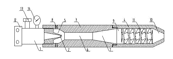
[0015] Such as figure 1 As shown, the self-suction air-type swirl foaming device for dust reduction in coal mines of the present invention is composed of a foaming liquid supply pipe 1, a jet nozzle 2, an air suction mixing cylinder 3 and a foaming cylinder 4. The foaming liquid supply pipe 1 of the joint 12, the pressure regulating valve 13 and the pressure gauge 14 is connected with the conical jet nozzle 2, and the air suction chamber 5, the gas-liquid mixing chamber 6, Diffused into a bubble chamber 7, the jet nozzle 2 is threaded into the suction chamber 5, two circular suction holes 8 are arranged on the wall of the suction chamber 5, and the diameter of the cylindrical gas-liquid mixing chamber 4 is the outlet of the jet nozzle 2 4~6 times of the diameter, the length of the gas-liquid mixing chamber 4 is 15~20 times of its own diameter, the distance...


PUM


Abstract

The invention discloses a self-absorption air type cyclone foaming device for dust removal of coal mine. The device mainly comprises a foaming liquid supply pipe, a jet flow nozzle, an air suction mixing barrel body and a foaming barrel body, wherein the foaming liquid supply pipe is connected with the jet flow nozzle; an air suction chamber, an air and liquid mixing chamber and a diffusion foaming chamber are sequentially arranged inside the air suction mixing barrel body; the jet flow nozzle is connected to the air suction chamber; an air suction hole is formed in the air suction chamber; and a cyclone foaming chamber and a foam flow-out chamber are sequentially arranged inside the foaming barrel body. Foaming liquid with set pressure is sprayed at high speed through the jet flow nozzle to form turbulent jet flow; under the suction of the turbulent jet flow, air in the environment can automatically enter the air suction chamber through the air suction hole and is brought into the air and liquid mixing chamber from the air suction chamber to perform energy transmission and mass transmission; the accelerated and compressed air is crushed into air bubbles by liquid drops in the diffusion foaming chamber; and the preliminarily foamed flow is fully foamed in the cyclone foaming chamber. The self-absorption air type cyclone foaming device is simple in structure, convenient to operate, high in foaming rate, low in energy consumption, safe, reliable and low in running and maintenance cost.

Description

technical field [0001] The invention relates to a foaming device, in particular to a self-suction air swirl foaming device for dust reduction. Background technique [0002] Practice at home and abroad has proved that foam dust suppression is one of the effective ways to improve the effect of mine dust control. In the foam dust suppression technology system, what kind of device is used to generate foam is one of its core contents. At present, there are mainly three types of foaming devices used for dust reduction: net type, pore type and Venturi type. The mesh foamer relies on mechanical ventilation to send the foaming liquid to the foaming net for foaming. Although the foam production is large, an additional fan is required to provide power, which consumes a lot of energy. The spray distance is short, and the foam cannot be effectively sent to the place where mining machinery cuts coal and rock dust; in addition, the range of water pressure and wind pressure that this foam...

Claims


Application Information

Patent Timeline
Patent Type & Authority Applications(China)
IPC IPC(8): B01D47/00B01F5/02B01F3/04E21F5/02
Inventor 王德明王和堂王庆国贾志强仲晓星
Owner CHINA UNIV OF MINING & TECH
Why Eureka
Try Eureka