Elastic rail fixing device
An elastic fixing device and track technology, applied in the field of rail transit, can solve the problems of the rails being unable to withstand upward force, having potential safety hazards, shortening the life of the rails, etc., achieving reasonable lateral stiffness and anti-yaw stiffness, and improving safety and comfort. the effect of improving the lateral stiffness
- Summary
- Abstract
- Description
- Claims
- Application Information
AI Technical Summary
Problems solved by technology
Method used
Image

Examples
Embodiment 1
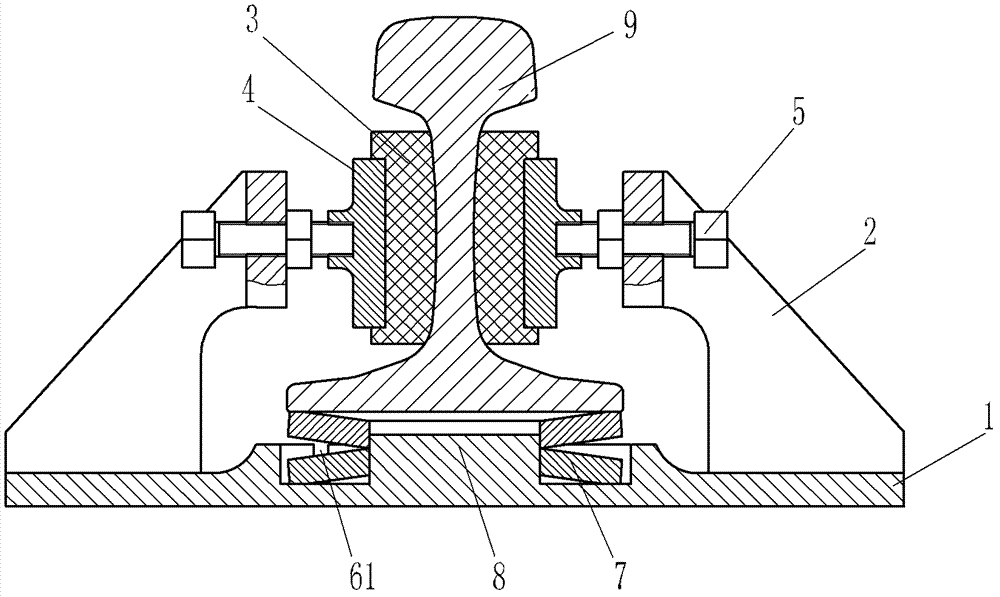
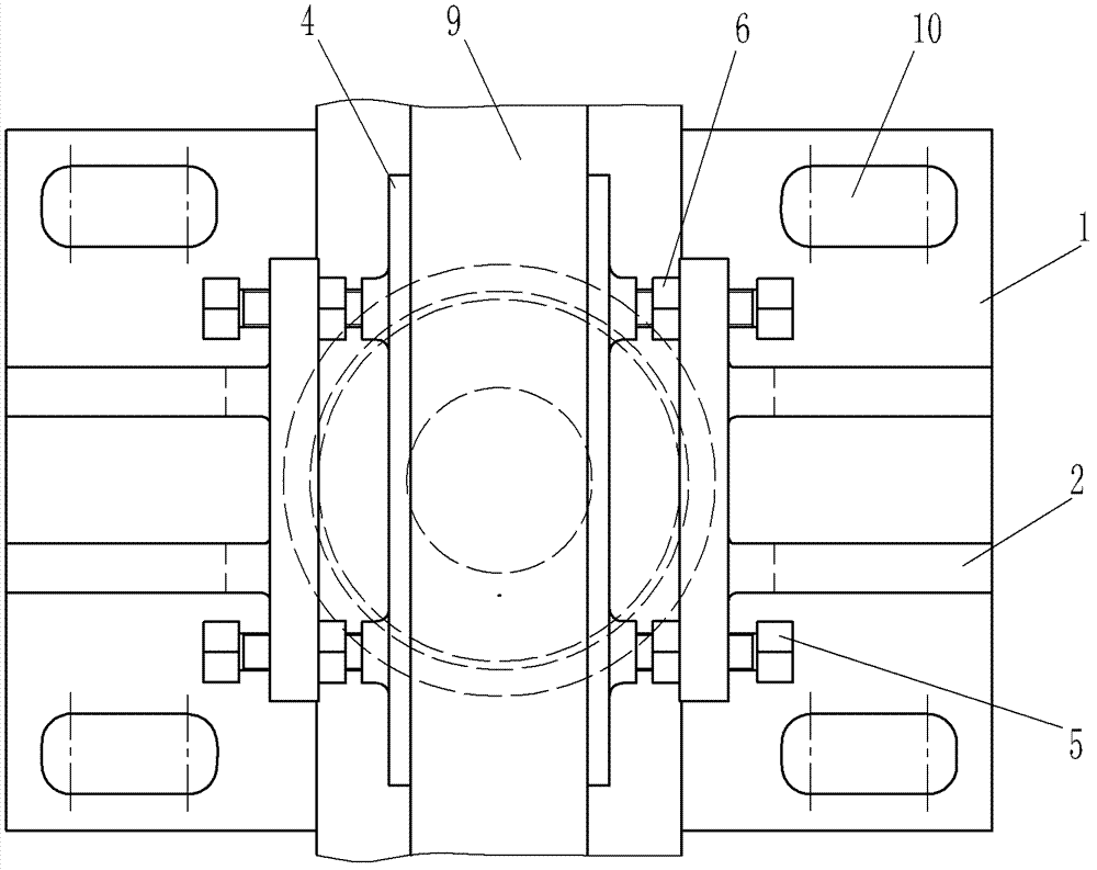
[0068] Such as figure 1 , figure 2 The rail elastic fixing device of the present invention shown includes a base 1 made of cast steel material, and also includes a guide assembly and a vertical support element. The guide assembly includes a guide element 3 and a guide bracket 2 located on both sides of the rail waist of the rail 9. The position adjustment bolt 5 is arranged on the guide bracket 2, and the guide element 3 is pressed against the rail waist surface of the rail 9 through the pressure plate 4 and the position adjustment bolt 5. Among them, there are two guide brackets 2, which are made of the same material as the base 1, and are cast into one body with the base 1; the guide element 3 is made of elastic polyurethane material, and the guide element is in close contact with the rail at the waist of the rail 9, and is vertically supported The element is made of a metal spring, specifically a metal disc spring 7 in the figure, which is located under the rail 9 and has...
Embodiment 2
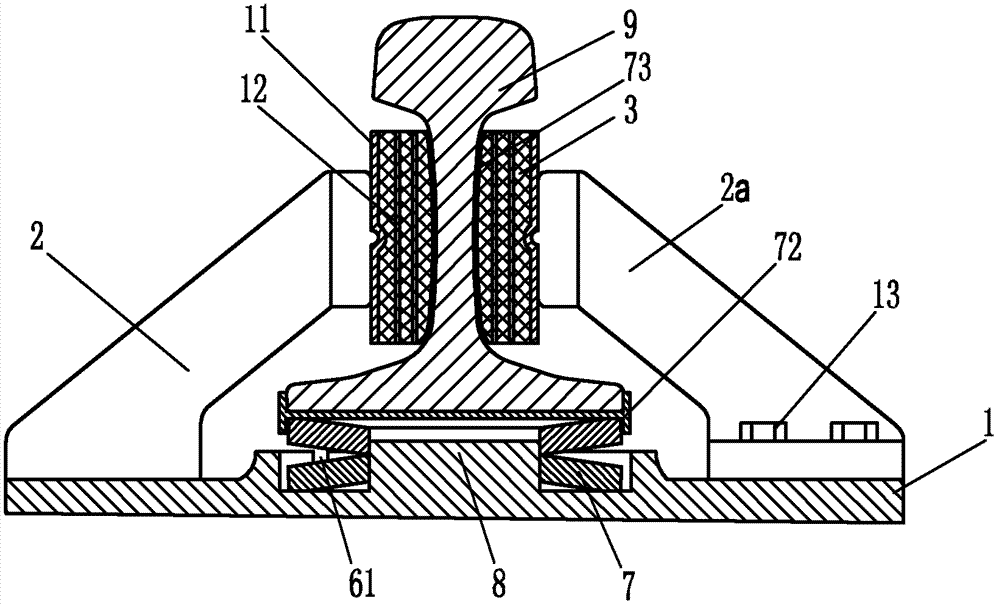
[0077] Such as image 3 , Figure 4 The rail elastic fixing device of the present invention shown differs from Embodiment 1 in that the guide assembly includes a guide bracket 2 cast integrally with the base 1 and a detachable guide bracket 2a, wherein the guide bracket 2a utilizes fasteners 13 fixed on base 1. Because a detachable guide bracket 2a is provided, the track elastic fixing device of the present invention can be easily assembled with the rail 9 and its relative position adjusted. Therefore, the guide bracket 2 and 2a are directly used to press the guide element 3 tightly on the rail waist. The mating surface of the guide element 3 and the rail adopts a profiling design, which keeps in close contact with the waist surface of the entire rail. In addition, in order to prevent the contact surfaces of the guide element 3 and the guide brackets 2 and 2a from wearing and tearing, a surface connecting plate 11 made of a steel plate is provided on the contact surface of t...
Embodiment 3
[0086] Such as Figure 5 , Image 6 The difference between the track elastic fixing device of the present invention and the second embodiment is that the guide element 3 is made of elastic polymer material, and rubber material is used in this example. Also arranged in the guide element 3 is a reinforcing element 12 consisting of a three-layer wire mesh arranged in the guide element 3 . There are grooves on the contact surface between the guide element 3 and the rail waist, which is conducive to adjusting the lateral elasticity and vertical elasticity of the guide element 3, and helps to dissipate heat. The elastic deformation of the element 3 can move relatively, and the guide element 3 does not need to slide between the guide bracket. Therefore, positioning holes are set on the surface connecting plate 11, and the corresponding guide brackets 2 and 2a are provided with positioning pins 14 that cooperate with the positioning holes. The two are fixedly connected to realize re...
PUM
| Property | Measurement | Unit |
|---|---|---|
| Lateral stiffness | aaaaa | aaaaa |
| Lateral stiffness | aaaaa | aaaaa |
| Lateral stiffness | aaaaa | aaaaa |
Abstract
Description
Claims
Application Information
 - Generate Ideas
- Intellectual Property
- Life Sciences
- Materials
- Tech Scout
- Unparalleled Data Quality
- Higher Quality Content
- 60% Fewer Hallucinations
Browse by: Latest US Patents, China's latest patents, Technical Efficacy Thesaurus, Application Domain, Technology Topic, Popular Technical Reports.
© 2025 PatSnap. All rights reserved.Legal|Privacy policy|Modern Slavery Act Transparency Statement|Sitemap|About US| Contact US: help@patsnap.com