Rotor clutch type motor-driven power generation turbocharger and auxiliary control circuit and control method thereof

An auxiliary control circuit and turbocharger technology, which is applied in the direction of engine components, combustion engines, machines/engines, etc., can solve the problems of high fuel consumption of engines, high consumption of exhaust gas energy, and low overall efficiency of turbochargers, etc., to improve Exhaust gas energy utilization rate, efficient distribution and utilization, and the effect of improving stability and reliability

Active Publication Date: 2013-05-08
BEIJING INSTITUTE OF TECHNOLOGYGY
View PDF9 Cites 26 Cited by
  • Summary
  • Abstract
  • Description
  • Claims
  • Application Information

AI Technical Summary

Problems solved by technology

[0005] In order to overcome the deficiencies of the existing technology and solve the problems of excessively high moment of inertia of the turbine rotor, excessive consumption of exhaust gas energy, low overall efficiency of the supercharger, and high fuel consumption of the engine caused by the middle motor generator, the present invention proposes a The motor generator turbocharger with rotor clutch device, its mot...

Method used


Image

  • Rotor clutch type motor-driven power generation turbocharger and auxiliary control circuit and control method thereof
  • Rotor clutch type motor-driven power generation turbocharger and auxiliary control circuit and control method thereof
  • Rotor clutch type motor-driven power generation turbocharger and auxiliary control circuit and control method thereof

Examples


Embodiment 1

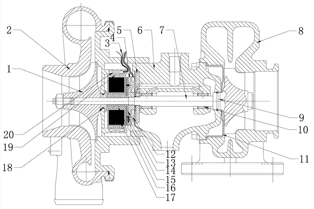
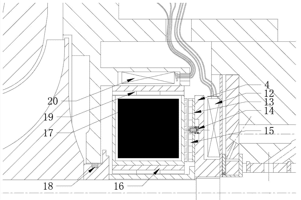
[0032] Such as figure 1 , figure 2 As shown, the electric generator turbocharger with the rotor clutch device of the present invention includes a compressor impeller 1, a compressor casing 2, an intermediate body 6, a turbine rotor 7, a turbine casing 8, a compressor back plate, a sealing sleeve, heat insulation sleeve 11, bearing, sealing ring, motor generator, electromagnetic clutch device and auxiliary control circuit, the rotor shaft and the turbine impeller fixed at one end of the rotor shaft constitute the turbine rotor 7, and the turbine impeller is located in the turbine shell 8, the compressor impeller 1 is assembled on the other end of the turbine rotor 7 and is located in the space formed by the compressor casing 2 and the compressor back plate, the compressor back plate cooperates with the turbine rotor 7 through a sealing sleeve, and the compressor A second sealing ring 18 is provided between the back plate and the sealing sleeve. The two ends of the intermediat...

Embodiment 2

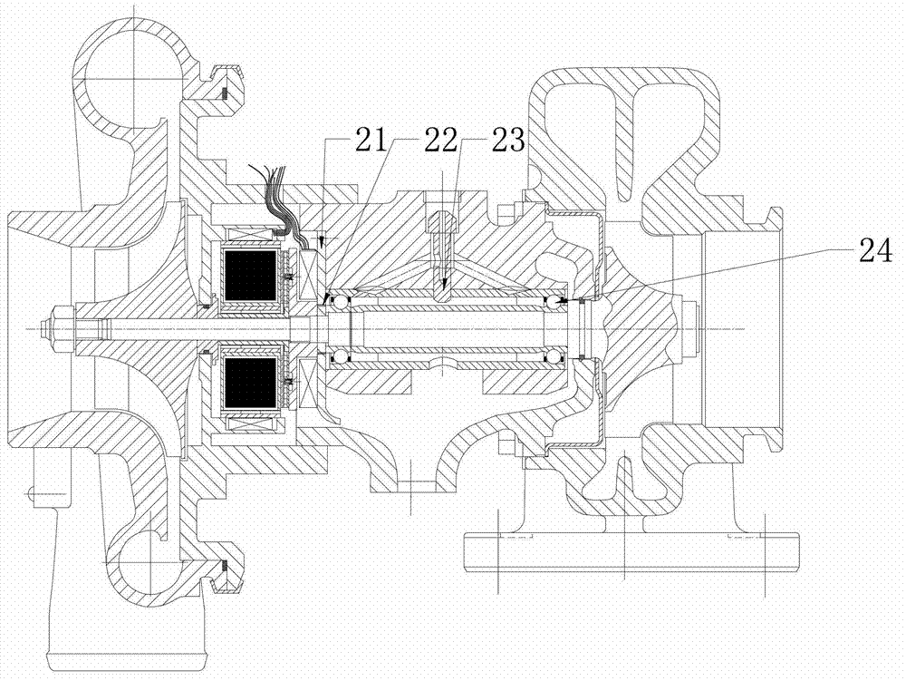
[0043] Such as image 3 , Figure 4 As shown, the main difference between this embodiment and Embodiment 1 is that the supporting bearing of the turbine rotor 7 is changed to an angular contact ball bearing 24, that is, the intermediate body 6 cooperates with the turbine rotor 7 through the angular contact ball bearing 24, and the outer angular contact ball bearing 24 The positioning mode of circle adopts positioning pin 23 to fix. Since the angular contact ball bearing 24 can withstand a certain radial load, the thrust bearing 5 on the side of the intermediate body 6 is omitted. One side of the motor generator is provided with an oil baffle 21, and a sealing device, such as a labyrinth oil seal, is installed at the junction of the oil baffle 21 and the shaft.


PUM


Abstract

The invention relates to a rotor clutch type motor-driven power generation turbocharger and an auxiliary control circuit and a control method thereof. A motor-generator, an electromagnetic clutch device and the auxiliary control circuit are installed on a turbine rotor of the turbocharger, wherein the electromagnetic clutch device and the auxiliary control circuit can control combination and separation between the motor-generator and the turbine rotor, and the motor-generator and the electromagnetic clutch device are both connected with the auxiliary control circuit through conductive wires. Under the control of the auxiliary control circuit, the turbocharger is respectively in three working states of motor-driven auxiliary supercharging, outage no-load and power generation energy storage. The electromagnetic clutch device is installed to achieve timely combination or separation between the motor-generator and the turbine rotor of the turbocharger. Rotational inertia of the turbine rotor is reduced, energy loss is reduced, stability and reliability of operation of the turbocharger are improved, fuel energy is effectively utilized, and efficient distribution and utilization of energy of the turbocharger are achieved. The rotor clutch type motor-driven power generation turbocharger has the advantages of being flexible and accurate to control.

Description

technical field [0001] The invention belongs to the field of vehicle power machinery, and in particular relates to a turbocharger equipped with a motor generator and capable of clutching a motor generator rotor and a turbine rotor. Background technique [0002] Turbocharging is one of the most important technical measures for internal combustion engine strengthening, energy saving and environmental protection. The engine turbocharger uses the exhaust gas energy discharged from the engine to drive the turbine, and the turbine drives the coaxial compressor to do work on the air, sending compressed air into the engine cylinder, increasing the air charge coefficient without increasing the engine cylinder volume, so that The engine injects more fuel, thereby increasing the engine output power, improving combustion, achieving the purpose of strengthening the engine and reducing emission pollution. Compared with naturally aspirated engines, contemporary turbocharging technology ca...

Claims


Application Information

Patent Timeline
IPC IPC(8): F02B37/14F02B39/00
CPCY02T10/144Y02T10/12
Inventor 黄若张威力陈富强陈静
Owner BEIJING INSTITUTE OF TECHNOLOGYGY
Why Eureka
Try Eureka