Three-valve hot-air engine

A hot gas engine and gas compressor technology, applied in hot gas variable displacement engine devices, machines/engines, mechanical equipment, etc., can solve problems such as heat loss and low fuel efficiency

Inactive Publication Date: 2013-05-08
ZEROQ SCI & TECH
View PDF9 Cites 5 Cited by
  • Summary
  • Abstract
  • Description
  • Claims
  • Application Information

AI Technical Summary

Problems solved by technology

[0003] Traditional internal combustion engines generally discharge high-temperature exhaust gas directly, resulting in serious heat loss
However, the gas working medium in the traditional heat engine needs heat to heat, the conventional heating method is

Method used


Image

  • Three-valve hot-air engine
  • Three-valve hot-air engine
  • Three-valve hot-air engine

Examples


Embodiment 1

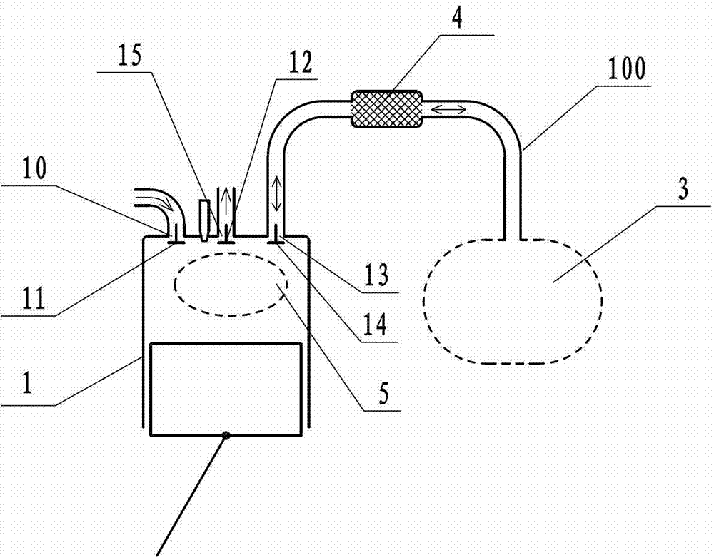
[0118] Such as image 3 The shown three-door hot gas engine comprises a cylinder-piston mechanism 1 and a combustion chamber 5, and the combustion chamber 5 is arranged in the cylinder-piston mechanism 1; an air inlet 10 is provided on the cylinder-piston mechanism 1, and the The air inlet 10 is provided with an intake valve 11, and the cylinder-piston mechanism 1 is provided with a reciprocating flow port 13, and the reciprocating flow port 13 is provided with a reciprocating flow control door 14; the cylinder-piston mechanism 1 is provided with The exhaust gas outlet 15 is provided with a exhaust valve 12, and the reciprocating flow port 13 communicates with the timing pulse gas mechanism 3 through the reciprocating communication channel 100, and the reciprocating communication channel 100 is provided with a heat recovery The regenerator 4 is equivalent to that the regenerator 4 communicates with the reciprocating flow port 13 at one end of the reciprocating communication ch...

Embodiment 2

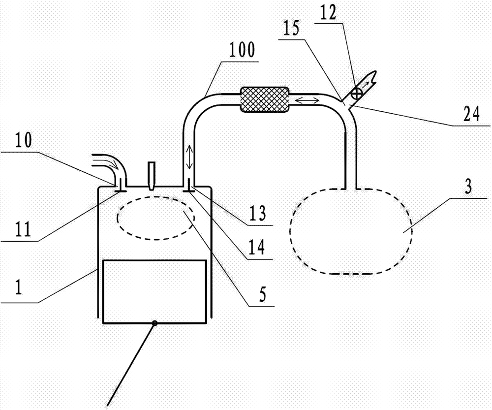
[0122] Such as Figure 4 The difference between the three types of door hot gas engines shown in Embodiment 1 is that a cooler 25 is provided on the auxiliary cylinder-piston mechanism 2 as the timing pulse gas mechanism 3, and a cooler 25 is installed on the regenerator A cooler 25 is also provided on the reciprocating communication passage 100 between 4 and the auxiliary cylinder-piston mechanism 2 .

[0123] Optionally, only any one of the above two coolers 25 may be provided.

[0124] Wherein, the highest pulse air pressure in the auxiliary cylinder-piston mechanism 2 as the timing pulse gas mechanism 3 is 0.8MPa.

Embodiment 3

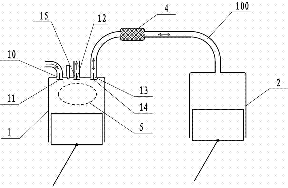
[0126] Such as Figure 5 The difference between the three types of door hot gas engines shown in Embodiment 1 is that the timing pulse gas mechanism 3 is set as an air storage tank 301 with a timing control mechanism 6, and the regenerator 4 passes through the The timing control mechanism 6 communicates with the gas storage tank 301 . Under the control of the timing control mechanism 6, the gas storage tank 21 sends gas into the cylinder of the cylinder-piston mechanism 1 of the three-type door hot gas engine according to the timing relationship, and receives the gas according to the timing relationship. Describe the gas in the cylinder of the cylinder-piston mechanism 1 to ensure that the engine can work according to the six-stroke cycle mode of intake stroke-compression stroke-combustion explosion power stroke-air supply stroke-recharge power stroke-exhaust stroke.

[0127] Wherein, the highest pulse pressure in the air storage tank 301 is 1 MPa.


PUM


Abstract

The invention discloses a three-valve hot-air engine, and the three-valve hot-air engine includes an air cylinder piston mechanism and a combustion chamber. An air cylinder of the air cylinder piston mechanism is provided with an air inlet. An air inlet valve is arranged at the position of the air inlet. The air cylinder of the air cylinder piston mechanism is provided with a reciprocating flow mouth which is provided with a reciprocating flow control valve. The reciprocating flow mouth is communicated with a timing pulse air mechanism through a reciprocating communicating channel. A heat regenerator is arranged on the reciprocating communicating channel. An exhaust air outlet is formed on the air cylinder of the cylinder piston mechanism, and an exhaust valve is arranged at the position of the exhaust air outlet. The combustion chamber is arranged inside the air cylinder piston mechanism. Due to the facts that the combustion motor is combined with the thermomotor, and the air exhausted from combustion motor is regarded as a circular working medium of a thermomotor, the further utility of the waste heat in the exhaust of the engine has the advantages of effectively improving thermal efficiency of the engine, and being simple in structure, strong in practicability, and broad in application prospect.

Description

technical field [0001] The invention relates to the field of thermal power, in particular to a heat engine. Background technique [0002] In recent years, the problems of high energy consumption and high pollution emissions of traditional internal combustion engines have become increasingly prominent. Therefore, heat engines have received extensive attention. However, heat engines heat the working fluid by means of external combustion heating. A working fluid with a higher temperature is obtained, therefore, causing a large amount of chemical loss. Not only that, due to the limited external combustion heating rate, high material requirements, and poor load response, the single-unit power and overall power density of the heat generator are severely restricted, and the use of the heat generator is severely limited in the end. [0003] Traditional internal combustion engines generally discharge high-temperature exhaust gas directly, resulting in serious heat loss. However, ...

Claims


Application Information

Patent Timeline
IPC IPC(8): F02G1/044F02G1/053F02G1/045
Inventor 靳北彪
Owner ZEROQ SCI & TECH
Why Eureka
Try Eureka