

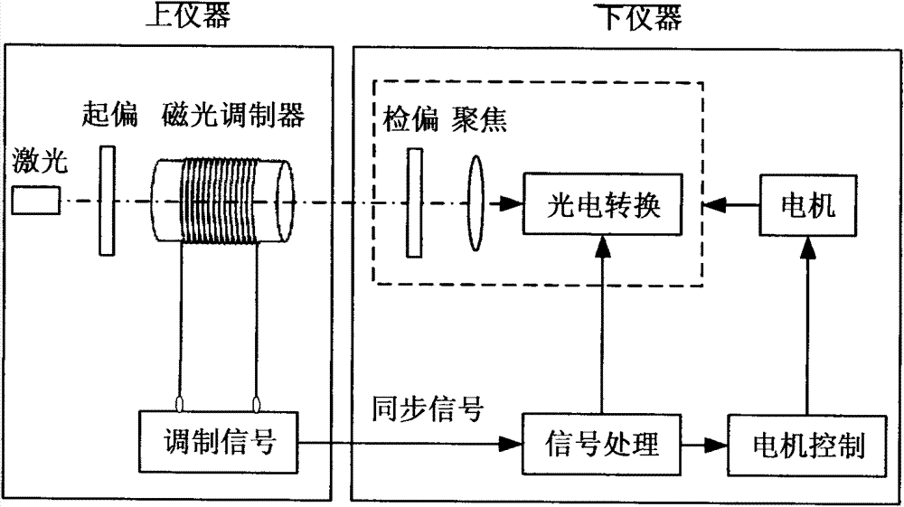
Space large-range azimuth automatic alignment method based magneto-optical modulation
A technology of magneto-optical modulation and automatic alignment, which is used in measuring devices, instruments, surveying and navigation, etc., and can solve problems such as no discovery.
- Summary
- Abstract
- Description
- Claims
- Application Information
AI Technical Summary
Problems solved by technology
Method used
Image

Examples
specific Embodiment approach
[0076] Now in conjunction with accompanying drawing, the specific embodiment of the present invention is set forth as follows:
specific Embodiment approach 1
[0077] Specific implementation mode 1: the situation where the distance between the upper and lower instruments is fixed
[0078] When the distance between the upper and lower instruments is fixed, here in m f =0.0087rad, k=10 as an example, assume the initial u provided by the manufacturer 0 is 1.05V, the initial misalignment angle α=-60°, and the signal collected after the corresponding magneto-optical modulation is processed by low-pass filtering to obtain a signal u=7.5V, and the two positions arbitrarily selected during the rotation of the instrument are α 1 =-30°, α 2 = 45°, and they respectively correspond to the signal u obtained by low-pass filtering the signal collected after magneto-optical modulation 01 =2.5V, u 02 =5V, the angle between the two positions β=75°.
[0079] Step 1: Set up the lower instrument at any position within the range of -90° to 90°, and measure the phase comparison between the modulated signal at this position and the AC signal obtained af...
specific Embodiment approach 2
[0092] Specific implementation mode two: the situation where the distance between the upper and lower instruments is uncertain
[0093] When the distance between the upper and lower instruments is different each time it is used, due to u 0 As an unknown quantity, the precise u should be obtained first by a certain method 0 . here m f = 0.0087 rad, u 0 =1V, k=10 as an example, set the initial position of the instrument as α1 =-25°, the measured signal u obtained after the magneto-optic modulation is processed by low-pass filtering 01 =8.214V; the signal u measured after the instrument rotates β=60° 02 = 6.71V.
[0094] Step 1: On the basis of the basic alignment of the upper and lower instruments, fix the position of the upper and lower instruments before using the instrument; when any initial misalignment angle α between the upper and lower instruments 1 ∈(-90°, 90°-β), set up the lower instrument in the pre-calibrated range of 0°~180°α 1 At the initial position of +90°...
PUM
 Abstract
Description
Claims
Application Information