
Strong light protecting module of photoelectric detection device

A technology for photoelectric detection and protection modules, applied in measurement devices, photometry, optical radiation measurement, etc., can solve the problems of breakdown damage of light receiving components, affecting the normal operation of detection systems, optical module failures, etc., to improve portability and reliability, easy debugging, stable performance

Active Publication Date: 2013-05-08
INST OF SEMICONDUCTORS - CHINESE ACAD OF SCI
View PDF5 Cites 2 Cited by
  • Summary
  • Abstract
  • Description
  • Claims
  • Application Information

AI Technical Summary

Problems solved by technology

[0004] In the actual application process, when the receiving end receives a strong optical signal, the optical receiving component is often damaged due to the lack of high-voltage protection measures in the receiving end circuit, resulting in the failure of the optical module and affecting the normal operation of the entire detection system

Method used


Image

  • Strong light protecting module of photoelectric detection device
  • Strong light protecting module of photoelectric detection device
  • Strong light protecting module of photoelectric detection device

Examples


example 1

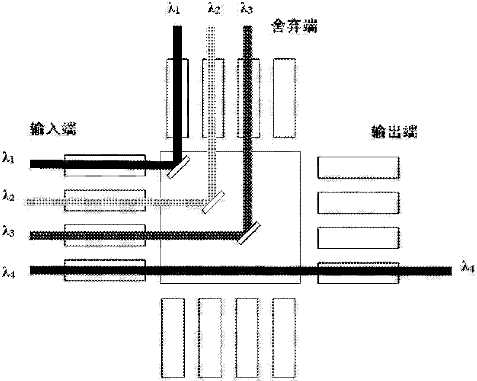
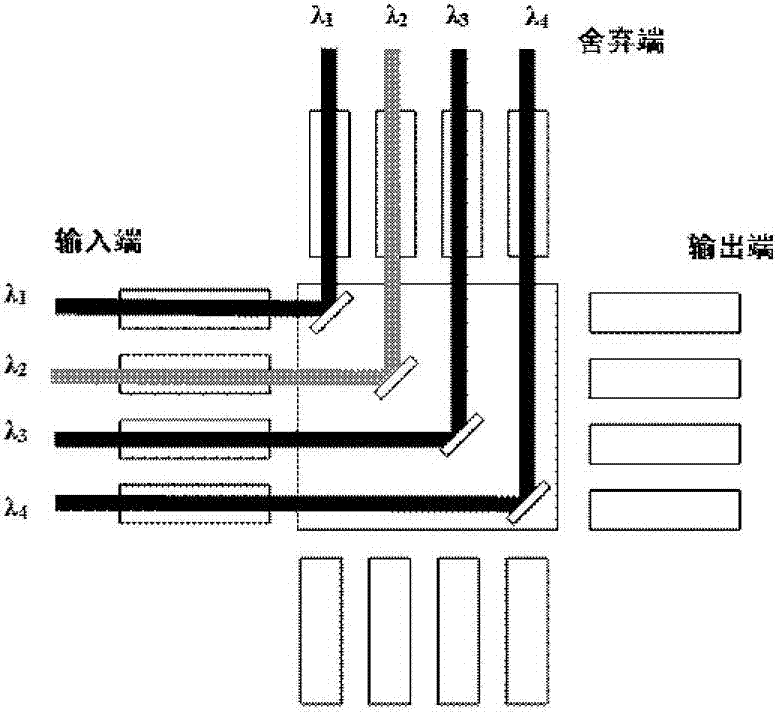
[0033] This example takes the two-dimensional mirror reflection type 4X4 MEMS optical switch as an example, where λ 1 , λ 2 , λ 3 is the non-operating wavelength, λ 4 is the working wavelength. figure 2 and image 3 They are two different working states of the optical switch in this example. figure 2 It is the working state of MEMS optical switch strong light protection. The spectral resolution function realizes strong light protection. image 3 It is the second working state of the strong light protection of the MEMS optical switch, and the time-resolved function realizes the strong light protection.

[0034] The MEMS optical switch is easy to integrate and control. The micromirror and the optical path of the two-dimensional optical switch are on the same plane. The micromirror has two states: on or off. By moving the mirror in the appropriate position to make the reflected beam, any input beam can be coupled for the output signal. An N×N MEMS micromirror matrix is ​...


PUM


Abstract

A strong light protecting module of a photoelectric detection device comprises a photoswitch, a photoelectric detection device and a control circuit. The photoswitch receives optical signals. The input end of the photoelectric detection device is connected with the output end of the photoswitch and the received optical signals are transformed to electrical signals through the photoelectric detection device. The input end of the control circuit is connected with the output end of the photoelectric detection device, and the signals from the photoelectric detection device are processed through the control circuit. By means of the strong light protecting module of the photoelectric detection device, the optical signals arriving at the surface of the photoelectric detection device are directly processed, the photoswitch is adopted so as to achieve filter function of the nonworking wavelength and time division on-off of the working wavelength, so that the system is enabled to be compact and simple and easy to integrate. The strong light protection of the receiving end of the photoelectric detection device is effectively carried out, and reliability and practicability of an optical module are improved.

Description

technical field [0001] The invention relates to a strong light protection module for a photoelectric detection device, which adopts optical switching to protect the receiving end of a photoelectric detection system from strong light, and suppresses noise (including background noise, interference noise, and return of short-range false targets). wave, atmospheric scattering interference, etc.), and distinguish the effective signal from the interference radiation. Background technique [0002] Optical switch is the key device of the new generation of all-optical network. It uses advanced optoelectronic integration technology to realize rapid optical signal switching, which can be used to realize the optical on-off function of one optical signal and the channel switching of multiple optical signals. It has a wide range of applications in optical protection systems, optical network testing and monitoring systems, and is suitable for long-distance, strong electromagnetic interfere...

Claims


Application Information

Patent Timeline
Patent Type & Authority Applications(China)
IPC IPC(8): G01J1/02
Inventor 林学春杨盈莹于海娟王文婷张景园
Owner INST OF SEMICONDUCTORS - CHINESE ACAD OF SCI
Learn More