Car body intensity fatigue and airtight fatigue test stand

A fatigue test and car body technology, which is applied in the direction of using liquid/vacuum for liquid tightness measurement, railway vehicle testing, etc. It can solve the problems that cannot be completed on the same test bench, and achieve convenient and fast testing and high testing efficiency. , the effect of low test cost

Active Publication Date: 2013-05-08
CHINA RAILWAYS CORPORATION +1
View PDF7 Cites 14 Cited by
  • Summary
  • Abstract
  • Description
  • Claims
  • Application Information

AI Technical Summary

Problems solved by technology

At present, the strength fatigue test and the airtight fatigue test cannot be completed on the same test bench

Method used


Image

  • Car body intensity fatigue and airtight fatigue test stand
  • Car body intensity fatigue and airtight fatigue test stand
  • Car body intensity fatigue and airtight fatigue test stand

Examples


specific Embodiment approach

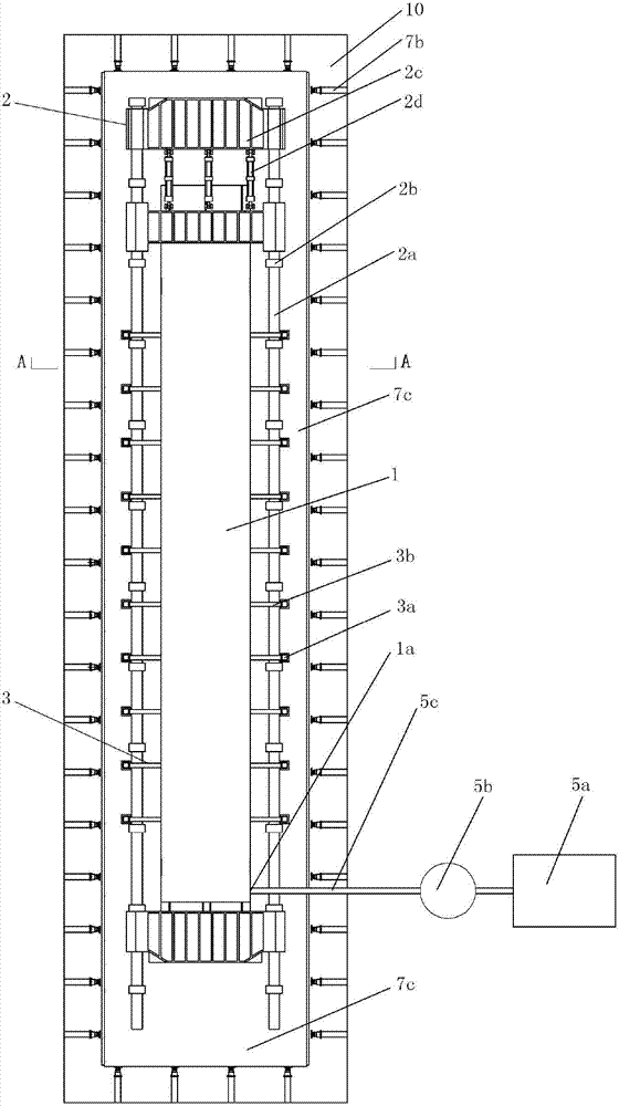
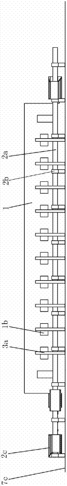
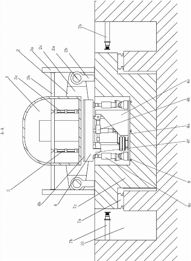
[0040] Figure 1~3Shown, a specific embodiment of this invention is: a car body strength fatigue and airtight fatigue test bench, including the car body 1 of the test train, the longitudinal loading device 2 at one end of the car body 1, and the car body 1 The vertical loading device 3 connected to the inner floor, a plurality of vibration excitation devices (usually three or more) installed under the car body 1, and the longitudinal loading device 2, the vertical loading device 3, and the vibration excitation device Hydraulic system; the vibration excitation device is a six-degree-of-freedom vibration device 4, and the six-degree-of-freedom vibration device 4, the longitudinal loading device 2, and the vertical loading device 3 are all installed in the pit 10 through a vibration isolation device , the vehicle body 1 is connected with the airtight device. in:

[0041] The specific composition of the vibration isolation device is: the inner bottom of the rectangular pot-shape...


PUM


Abstract

Disclosed are car body intensity fatigue and an airtight fatigue test stand. The car body intensity fatigue and the airtight fatigue test stand comprise a car body tested for a train, a longitudinal loading device, a vertical loading device and a plurality of shock excitation devices installed below the car body. The shock excitation devices are six degree of freedom shock excitation devices. The six degree of freedom shock excitation devices, the longitudinal loading device and the vertical loading device are installed in a pit through a vibration isolation device. Air vents of the car body are connected with an airtight device. The vibration isolation device specifically comprises a rectangular basin shaped base inner bottom is connected with base plates of the six degree of freedom shock excitation devices through a T-typed guiding rail. The longitudinal loading device and the vertical loading device are fixed on the upper surface of a side edge of the base. The side edge of the base is connected with a wall of the pit through a buffering rubber-metal pad. The lower surface of the base is connected with a step of the pit through an air spring. Intensity fatigue test can be carried out. Full-scale car body airtight fatigue test can be completed. The car body intensity fatigue and the airtight fatigue test stand are low in testing cost, high in testing efficiency, authentic and reliable in testing results. Influences towards the surrounding environment are small when the car body intensity fatigue and the airtight fatigue test stand are tested.

Description

technical field [0001] The invention relates to a test bench for the fatigue strength of the body structure of a railway locomotive vehicle body and airtight load fatigue. Background technique [0002] The development of railway transportation to high-speed and heavy-duty has aggravated the vibration of the train running, the service environment of each component has deteriorated, and the structural strength problems exposed to the bogie, wheel axle and car body have gradually increased, especially in the light structure required by high-speed trains. After quantification, the problem of structural strength will be more prominent. [0003] Moreover, with the high speed of railway vehicles, railway vehicles, especially EMU vehicles, will cause large air pressure fluctuations outside the vehicles when they meet or run in tunnels. When trains meet frequently on the line or pass through tunnels, alternating airtight pressure loads will be formed on the trains. Generally speaki...

Claims


Application Information

Patent Timeline
Patent Type & Authority Applications(China)
IPC IPC(8): G01M17/08G01M3/02
Inventor 张卫华邬平波宋烨王建斌罗仁吴会超
Owner CHINA RAILWAYS CORPORATION
Why Eureka
Try Eureka