
Material emissivity measuring method based on infrared thermometer

A technology of infrared thermometer and measurement method, which is used in material excitation analysis, optical radiation measurement, material analysis, etc., and can solve the problems of poor measurement result accuracy, slow measurement speed, and complicated use.

Active Publication Date: 2013-05-08
HARBIN INST OF TECH
View PDF5 Cites 21 Cited by
  • Summary
  • Abstract
  • Description
  • Claims
  • Application Information

AI Technical Summary

Problems solved by technology

[0004] The purpose of the present invention is to solve the problems of poor measurement accuracy, complex use and slow measurement speed of existing material emissivity measurement methods. The present invention provides a material emissivity measurement method based on an infrared thermometer

Method used


Image

  • Material emissivity measuring method based on infrared thermometer
  • Material emissivity measuring method based on infrared thermometer
  • Material emissivity measuring method based on infrared thermometer

Examples


specific Embodiment approach 1

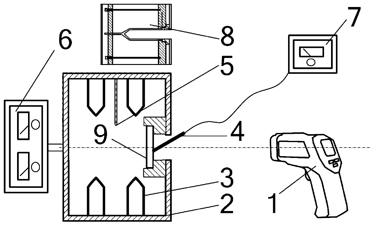
[0059] Specific implementation mode one: see figure 1 To illustrate this embodiment, the material emissivity measurement method based on an infrared thermometer described in this embodiment is realized by using an infrared thermometer 1, a thermocouple probe 4, a thermocouple thermometer 7, a black body furnace 8 and a temperature control system For the measurement of material emissivity, the temperature control system includes a heating furnace 2, a heater 3, a temperature acquisition device 5 and a temperature inspection controller 6, and the heating furnace 2 is provided with a circular light hole to realize material emission The rate measurement process is:

[0060] Step 1. First, the material to be tested is made into a circular test piece 9, wherein the material to be tested is an opaque material, and then the entrance pupil of the infrared thermometer 1 is aligned with the light transmission hole of the blackbody furnace 8. The blackbody furnace The emissivity of 8 is ...

specific Embodiment approach 2

[0071] Specific embodiment 2: The difference between this embodiment and specific embodiment 1 is that the stray radiation energy is calculated using the stray radiation subtraction algorithm described in the step 1, and the specific method is as follows:

[0072] The operating band of the infrared thermometer 1 is an atmospheric window, and the temperature measurement formula of the infrared thermometer 1 is expressed as,

[0073] ε′f(T m )+(1-ε′)f(T e ) = εf(T r )+(1-α)f(T e )+g(T e ) (1)

[0074] In the formula, T m is the temperature measured by infrared thermometer 1, unit K;

[0075] T r is the real temperature of the tested circular test piece 9, unit K;

[0076] T e is ambient temperature, unit K;

[0077] ε is the emissivity of the tested circular specimen 9;

[0078] ε' is the emissivity setting for the infrared thermometer 1;

[0079] α is the surface absorptivity of the tested circular test piece 9;

[0080] g(T e ) is stray radiant energy;

[00...

specific Embodiment approach 3

[0096] Embodiment 3: The difference between this embodiment and Embodiment 2 is that in the step 7, the material emissivity ε of the material to be tested is calculated in the temperature range from room temperature to 1500°C. The specific implementation method is as follows:

[0097] The material emissivity ε expression is as follows,

[0098] ϵ = ϵ ′ ( T m n - T e n ) - g ( T e ) C T r ...


PUM


Abstract

The invention discloses a material emissivity measuring method based on an infrared thermometer and belongs to the technical field of thermal performance measurement of high-temperature opaque materials. The method disclosed by the invention aims to solve the problems that conventional material emissivity measuring methods are poor in measuring result accuracy, complex in use and low in measuring speed. The method disclosed by the invention comprises the following steps of firstly measuring the temperature of a blackbody furnace by using an infrared thermometer, obtaining the stray radiation energy received by the infrared thermometer through calculating, measuring the surface temperature of a test piece made from the to-be-measured material by using a thermocouple thermodetector and obtaining the true surface temperature of the test piece. According to the invention, five measuring temperature values are obtained through measuring the surface temperature of the test piece under the condition of five set emissivities of the infrared thermometer; five material emissivities are obtained through bringing the five set emissivities and the five measuring temperature values into a calculating formula; and the emissivity of the to-be-measured material is obtained through taking the average. The method disclosed by the invention is mainly applied to the technical field of emissivity measurement of the high-temperature opaque materials.

Description

technical field [0001] The invention relates to a material emissivity measurement method based on an infrared thermometer and a measurement method for subtracting stray radiation, and belongs to the technical field of thermophysical property measurement of high-temperature opaque materials. Background technique [0002] Emissivity is defined as the ratio of the surface radiant energy of a material to the radiant energy of a black body at the same temperature. The emissivity of the surface of various materials is a physical quantity that characterizes the radiation ability of the surface of the material, and is an extremely important thermophysical parameter. According to the wavelength range, the emissivity can be divided into full-spectrum emissivity, spectral emissivity and band emissivity; according to the measurement direction, it can be divided into hemispherical emissivity and directional emissivity. [0003] The measurement of material emissivity involves many fields...

Claims


Application Information

Patent Timeline
Patent Type & Authority Applications(China)
IPC IPC(8): G01N21/00G01N21/71G01J5/00
Inventor 牛春洋齐宏王大林阮立明姜宝成
Owner HARBIN INST OF TECH
Learn More