Luminous communication indication connecting line

A technology of communication connection and connection line, which is applied in the application field of communication line connection

Active Publication Date: 2013-05-08
SHANGHAI KEYAN PHOSPHOR TECH
View PDF14 Cites 5 Cited by
  • Summary
  • Abstract
  • Description
  • Claims
  • Application Information

AI Technical Summary

Problems solved by technology

At the same time, the above patents only use a simple combination of light-emitting wires and wires, and use circuits to control flashing, and their voltage and power still maintain a high-voltage and high-power state.

Method used


Image

  • Luminous communication indication connecting line
  • Luminous communication indication connecting line

Examples


Embodiment

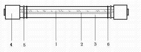
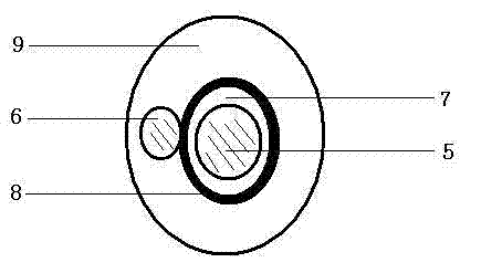
[0041] A metal copper wire with a diameter of 0.05 mm is used, and its surface is coated with a light-emitting layer, and the light-emitting layer uses a commercially available D502S electroluminescence material. The electroluminescence material is mixed with high insulating UV resin and cyanoethyl ether to uniformly coat the surface of the copper wire with a thickness of 15 microns. Use UV ultraviolet curing for 3 seconds.

[0042] There is a transparent conductive layer outside the light-emitting layer, and the transparent conductive layer is a conductive polymer.

[0043] The outside of the transparent conductive layer is connected to the outer electrode of a metal copper wire with a diameter of 0.05 mm, and sealed with a colored transparent plastic PE to complete the preparation of an electroluminescent wire with a diameter of 0.3 mm.

[0044] The electroluminescent wire and the optical fiber are combined with PVC, and a wire extruder is used to mold a continuous 500-meter-...


PUM


Abstract

A luminous communication indication connecting line comprises a communication transmission line provided with an electrogenerated luminous line, and two end attachment plugs, and is characterized in that the communication transmission line is a communication wire or an optical fiber, and the communication transmission line accompanies with the electrogenerated luminous line in a parallel mode and is sealed through transparent plastics to form the transmission line provided with the electrogenerated luminous line; two ends of the communication transmission line are respectively matched with a communication attachment plug, and electrodes of the electrogenerated luminous line are exposed outside the communication attachment plugs; and a hand-held mobile actuator is connected with the electrodes of the electrogenerated luminous line to give out light, the position and the direction of the communication transmission line are determined, maintenance detection staff can determine a faulty line in a few seconds, and working efficiency is improved.

Description

technical field [0001] The invention belongs to the technical field of communication line connection application. Background technique [0002] The existing communication lines basically use optical fiber or metal wires as the main body, and their main function is to transmit data. Due to the advancement of information technology, there are a large number of communication signal connection lines cross-connected in the switching equipment of the communication data connection switching processing center. When one of them fails, maintenance personnel cannot find out the corresponding connection positions of the two ends of the faulty line from thousands of densely distributed lines. In addition, in the telecommunications data exchange center, there are a large number of groups of data transmission lines distributed in the ceiling, walls, underground, etc., and it is impossible to determine the direction and corresponding position when repairing and replacing a single line or mu...

Claims


Application Information

Patent Timeline
Patent Type & Authority Applications(China)
IPC IPC(8): H05B33/14
Inventor 郑岩费运启耿树范边静宇史陈峰孟立建徐征
Owner SHANGHAI KEYAN PHOSPHOR TECH
Why Eureka
Try Eureka