Auxiliary brake device applied to non-drive axle

A non-drive axle, auxiliary braking technology, applied in the direction of brakes, brake components, brake types, etc., can solve the problems of heavy load, overheating of brake drums and brake pads, affecting driving safety, etc., to reduce The effect of maintenance cost, reduction of maintenance frequency, and traffic accident avoidance

Inactive Publication Date: 2013-05-15
XIAMEN YULONG MACHINERY +1
View PDF8 Cites 20 Cited by
  • Summary
  • Abstract
  • Description
  • Claims
  • Application Information

AI Technical Summary

Problems solved by technology

However, due to the heavy load of trailers, semi-trailers, heavy trucks, and large passenger cars, when encountering mountainous roads and long downhills, due to frequent braking and long-term braking, the brake drum and brake friction lining will overheat. , reduce the braking efficiency of the car, and even the braking ability completely disappears in severe cases, causing traffic accidents
[0003] In addition, for the semi-trailer, the semi-trailer will collide with the tractor due to the lag of the semi-trailer relative to the tractor when braking, especially on rainy and snowy roads, when descending steep slopes and turning. In severe cases, folding will occur and the vehicle will be damaged. Seriously affect driving safety and easily cause major traffic accidents

Method used


Image

  • Auxiliary brake device applied to non-drive axle
  • Auxiliary brake device applied to non-drive axle
  • Auxiliary brake device applied to non-drive axle

Examples


Embodiment 1

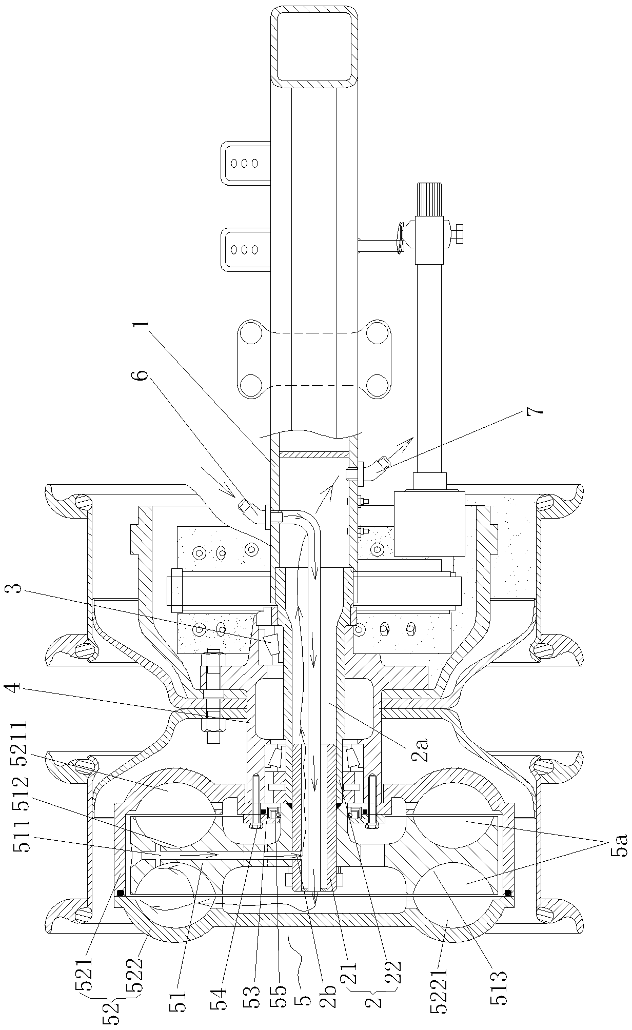
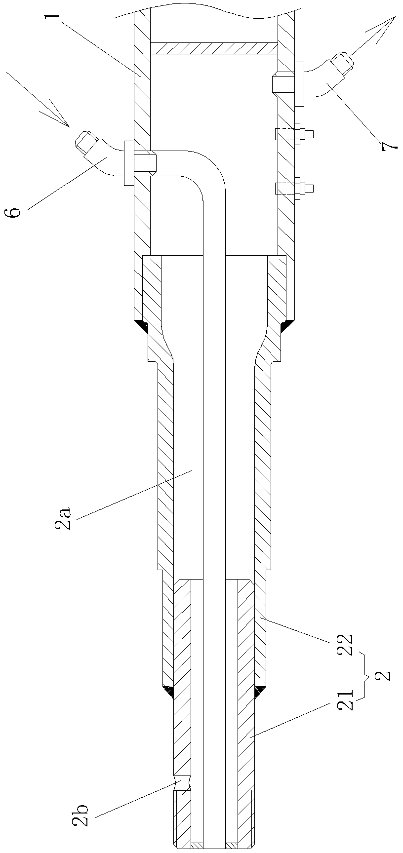
[0028] Example one figure 1 , figure 2 , image 3 As shown, an auxiliary braking device applied to a non-driving axle includes an axle housing 1 of the non-driving axle. Both ends of the axle housing 1 are fixed with axle heads 2, and the outer surface of each axle head 2 passes through a bearing 3 is connected to the hub 4, a hydraulic retarder 5 is installed between the end of the hub 4 and the shaft head 2, and each shaft head 2 is provided with an axial through hole 2a, and the axial through hole 2a constitutes A part of the oil passage of the hydraulic retarder 5, and the oil inlet pipe 6 and the oil return pipe 7 are installed on the axle housing 1;

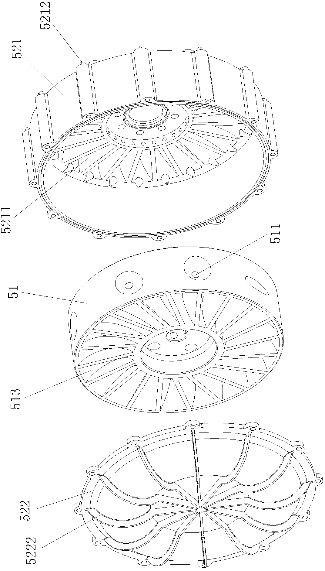
[0029] The hydraulic retarder 5 includes a stator impeller 51 fixed on the outer surface of the end of the shaft head 2, and a rotor impeller 52 that is wrapped around the stator impeller 51 and fixed to the hub 4. The inner surface of the rotor impeller 52 A hydraulic oil working chamber 5a is formed between the outer surfac...

Embodiment 2

[0045] Embodiment two Figure 5 , Image 6 , Figure 7 As shown, the difference from the first embodiment is that the end face of the stator impeller 51 and the front rotor impeller 522 is not provided with multiple damping slots, and the end face of the front rotor impeller 522 and the stator impeller 51 is also not provided with multiple phases. Corresponding damping groove;

[0046] The outer surface of each shaft head 2 close to the hydraulic oil working chamber 5a is radially provided with a radial oil inlet 2c communicating with the axial through hole 2a, and the stator impeller 51 is provided with an oil passage 513 and the radial The oil inlet 2c is matched, the oil return pipe 7 passes through the axial through hole 2a of the shaft head 2 to communicate with the hydraulic oil working chamber 5a, and is close to the axial through hole 2a of the shaft head 2 of the hydraulic oil working chamber 5a. A seal is formed between the inner surface of the axle housing 1 and the o...


PUM


Abstract

The invention discloses an auxiliary brake device applied to a non-drive axle. The auxiliary brake device applied to the non-drive axle comprises an axle shell of the non-drive axle, wherein shaft heads are respectively fixed at two ends of the axle shell, the outer surface of each shaft head is connected with a wheel hub through a bearing, a hydraulic retarder is arranged between the wheel hub and an end portion of each shaft head, each hydraulic retarder comprises a stator impeller fixed on the outer surface of the end portion of each shaft head and a rotor impeller which is covered outside each stator impeller and fixed with the wheel hub, and a hydraulic oil work cavity is formed between the inner surface of each rotor impeller and the outer surface of each stator impeller. An oil inlet pipe and an oil return pipe are arranged on the axle shell, each shaft head is provided with an axial through hole, each axial trough hole forms a part of an oil pipeline passage of each hydraulic retarder, and the oil inlet pipe and the oil return pipe are communicated with the hydraulic oil work cavities through the axial through holes in the shaft heads. The auxiliary brake device applied to the non-drive axle is capable of effectively improving the brake capacity of vehicles, especially a trailer, a semitrailer, a heavy truck and a large bus, and guarantees driving safety.

Description

Technical field [0001] The invention relates to the technical field of automobile chassis manufacturing, in particular to an auxiliary braking device applied to a non-driving axle. Background technique [0002] The braking of the non-driving wheels of existing trailers, semi-trailers, heavy goods vehicles, and large passenger vehicles basically adopts the friction between the brake friction lining and the brake drum in the wheel hub to achieve braking. However, due to the heavy load of trailers, semi-trailers, heavy goods vehicles, and large buses, when encountering mountain roads and long downhills, frequent braking and long-term braking will cause the brake drum and brake pads to overheat , Reduce the braking efficiency of the car, and even the braking ability completely disappears in severe cases, causing traffic accidents. [0003] In addition, for semi-trailers, the lag of the semi-trailer relative to the tractor may cause the semi-trailer to collide with the tractor, especia...

Claims


Application Information

Patent Timeline
Patent Type & Authority Applications(China)
IPC IPC(8): B60T1/087B60T10/02
Inventor 李振营廖德峰曾锋陈卿雁陈益明
Owner XIAMEN YULONG MACHINERY
Why Eureka
Try Eureka