
Damage detection device for lasher vision conveying belt

A damage detection and conveyor belt technology, which is applied to conveyor control devices, conveyor objects, transportation and packaging, etc., can solve the problems that the complexity of image processing algorithms cannot meet the needs of online real-time detection operations, economic losses, and high costs. The effect of easy installation and mobile detection, simple system structure and low cost

Inactive Publication Date: 2013-05-15
JIANGYIN ZHONGKE MINING SAFETY TECH +1
View PDF7 Cites 16 Cited by
  • Summary
  • Abstract
  • Description
  • Claims
  • Application Information

AI Technical Summary

Problems solved by technology

[0003] Longitudinal tearing accidents of the conveyor belt caused by impurities occur from time to time. If it is not found in time, the entire conveyor belt will be torn and damaged, resulting in huge economic losses.
In order to solve this technical problem, experts at home and abroad have tried to use many methods for anti-tear detection, but due to certain defects in the principle of many detection methods, or high cost, cumbersome maintenance and other reasons, the accuracy cannot be guaranteed. , Stable realization of the purpose of conveyor belt tear detection
Among them, the visual method is a newly proposed detection method in recent years. Its advantage is that it is non-contact and does not require equipment modification. However, due to the complexity of the image processing algorithm, it cannot meet the operational requirements of online real-time detection, and has not been applied in actual production.

Method used


Image

  • Damage detection device for lasher vision conveying belt

Examples


Embodiment Construction

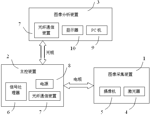
[0025] see figure 1 , the present invention relates to a laser vision conveyor belt damage detection device, which is mainly composed of an image acquisition device 1, a main control device 2 and an image analysis device 3, the image acquisition device 1 and the main control device 2 are connected by a cable, and the The image analysis device 3 is connected to the main control device 2 through an optical cable.

[0026] The image acquisition device 1 includes a laser 4 and a camera 5, and its function is to collect a laser image on the surface of the conveyor belt and transmit it to the main control device 2 for processing in real time. The laser 4 projects a red light with a wavelength of 650nm to the surface of the conveyor belt. Laser stripes are used as structured light for auxiliary measurement. The direction of the laser line is perpendicular to the conveying direction of the conveyor belt. The camera 5 is arranged on one side of the laser 4, and both the camera 5 and th...


PUM


Abstract

The invention relates to a damage detection device for a lasher vision conveying belt. The damage detection device for the lasher vision conveying belt comprises an image capture device (1), a master control device (2) and an image analysis device (3). The image capture device (1) comprises lasher devices (4) and cameras (5), the lasher devices (4) and the cameras (5) are arranged on one side of the conveying belt in pairs, the lasher devices (4) are perpendicularly arranged over the conveying belt, and the lasher devices (4) and the cameras (5) are arranged at a certain included angle. The master control unit (2) comprises a signal processor (6), an optical fiber communication device (7) and a power supply (8), and the image analysis device (3) comprises the optical fiber communication device (7), a personal computer (PC) machine (9) and a displayer (10). According to the damage detection device for the lasher vision conveying belt, no ionizing radiation or electromagnetic radiation exists and the problems that the algorithm of a machine vision detection method is too complex in the damage feature exaction process of the conveying belt is solved.

Description

technical field [0001] The invention relates to a conveyor belt damage detection device, in particular to a conveyor belt safety detection device for detecting the tearing and skin damage of the conveyor belt according to laser line scanning images. Background technique [0002] Since its invention in 1795, the belt conveyor has been widely used in electric power, metallurgy, coal, chemical industry, mining, port and other industries after nearly two centuries of development. It has the characteristics of large transportation volume, continuous transportation and high strength. It is a relatively economical and reliable transportation equipment in coal mine production, which has been widely used and has become the main transportation equipment for underground raw coal transportation. [0003] Longitudinal tearing accidents of the conveyor belt caused by impurities occur from time to time. If it is not found in time, the entire conveyor belt will be torn and damaged, resultin...

Claims


Application Information

Patent Timeline
IPC IPC(8): B65G43/02
Inventor 朱红岩胡鹏余意
Owner JIANGYIN ZHONGKE MINING SAFETY TECH
Learn More