Hot water system of heat pump

A technology of heat pump hot water and heat exchangers, which is applied in the direction of fluid heaters, lighting and heating equipment, etc., can solve the problem of high cost, achieve the effect of increasing temperature difference, enhancing heating efficiency, and improving heat exchange capacity

Active Publication Date: 2013-05-15
IND TECH RES INST
View PDF7 Cites 2 Cited by
  • Summary
  • Abstract
  • Description
  • Claims
  • Application Information

AI Technical Summary

Problems solved by technology

However, although this method is effective, it is expensive

Method used


Image

  • Hot water system of heat pump
  • Hot water system of heat pump
  • Hot water system of heat pump

Examples


Embodiment Construction

[0042] The implementation of the present invention is described below by means of specific examples, and those skilled in the art can easily understand other advantages and effects of the present invention from the content disclosed in this specification. The present invention can also be implemented or applied by other different specific embodiments.

[0043] It should be noted that the structures, proportions, sizes, etc. shown in the drawings attached to this specification are only used to match the content disclosed in the specification, and are understood and read by those skilled in the art, and are not used to limit the implementation of the present invention. condition, so it has no technical substantive meaning, and any modification of structure, change of proportional relationship or adjustment of size shall still fall within the scope of the present invention without affecting the effect and purpose of the present invention. The disclosed technical content must be w...


PUM


Abstract

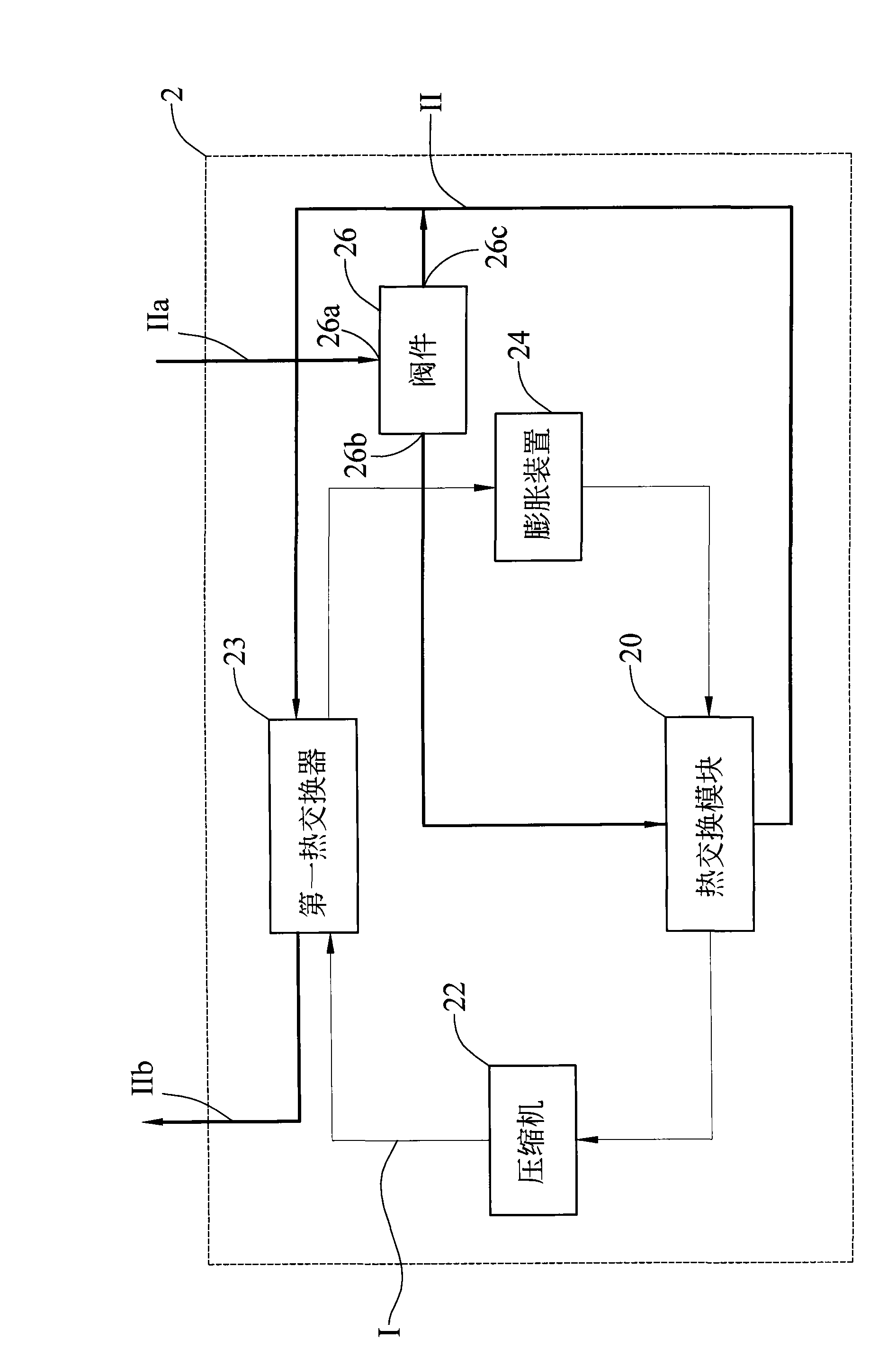
The invention provides a hot water system of a heat pump, which comprises a refrigerant loop pipeline formed by the serial connection of a compressor, a first heat exchanger, an expansion unit and a heat exchange module, and a liquid-cycle-cooling pipeline connected with a valve, the heat exchange module and the first heat exchanger. The heat exchange module comprises a second heat exchanger and an efficiency enhancer. Liquid flows from the input pipe of the liquid-cycle-cooling pipeline to the efficiency enhancer of the heat exchange module after flowing through the valve, and then flows out of the output pipe of the liquid-cycle-cooling pipeline after flowing through the first heat exchanger. When the liquid flows through the heat exchange module, heat exchange is carried out between the liquid and a refrigerant in the efficiency enhancer. Therefore, the temperature of the refrigerant is increased before the refrigerant flows into the compressor. When the liquid flows through the first heat exchanger, heat exchange is carried out between the liquid and a refrigerant in the first heat exchanger. Therefore, the temperature of the liquid flowing out of the output pipe of the liquid-cycle-cooling pipeline is increased.

Description

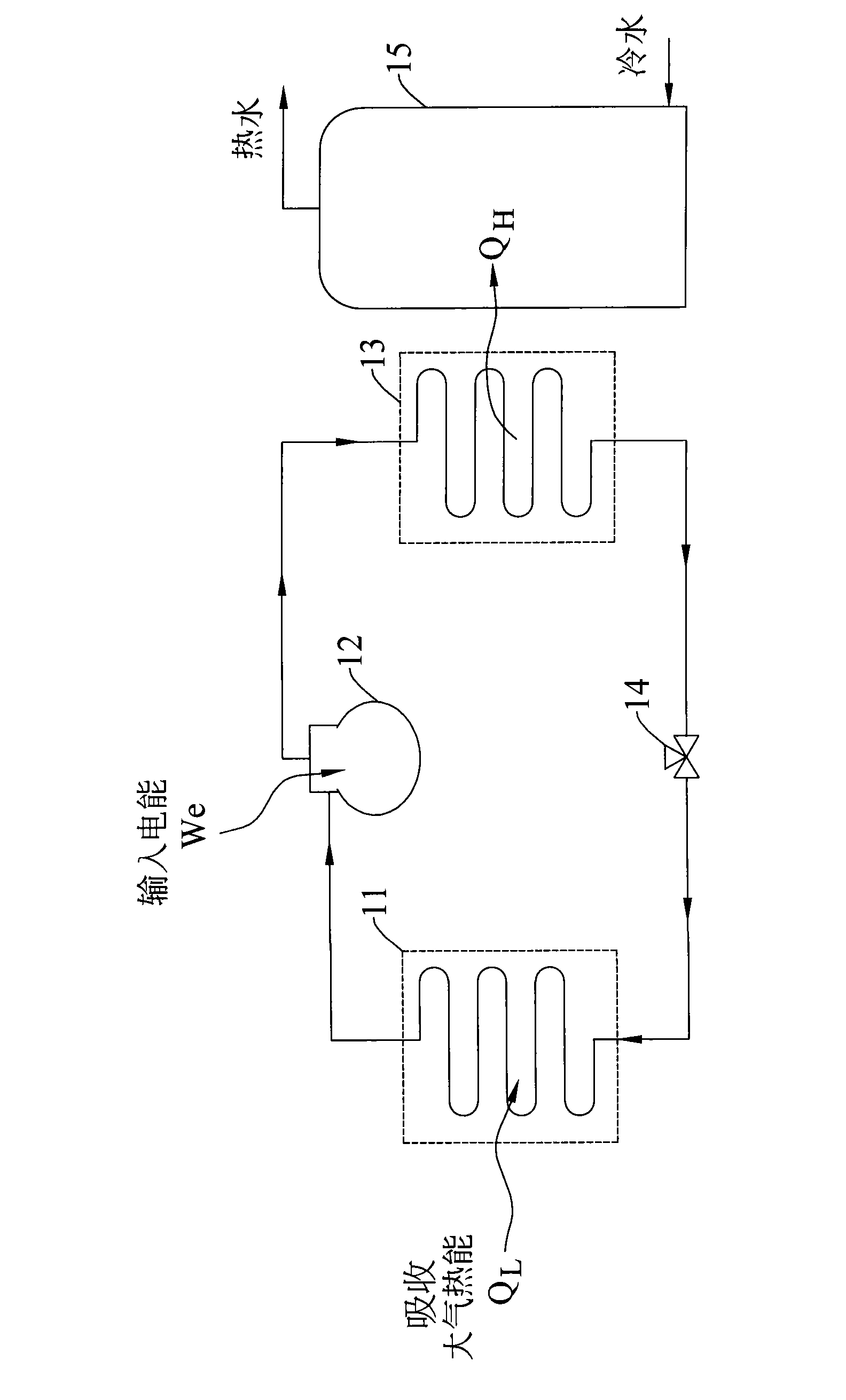
technical field [0001] The invention relates to a heat pump water heating system, in particular to a heat pump water heating system capable of improving heating efficiency. Background technique [0002] The heat pump hot water system is designed according to the reverse-Rankine cycle (Rankine cycle), using the compressor to compress the gaseous refrigerant into a high-temperature and high-pressure superheated refrigerant to heat the liquid, and expand it through the constant enthalpy of the expansion valve to become a low-temperature and low-pressure refrigerant. Refrigerant, and then through a fin-tube heat exchanger (such as an evaporator) to obtain heat from the outside of the heating equipment. [0003] like figure 1 As shown, it schematically shows the basic components of a traditional heat pump water heating system. The heat pump water heating system mainly includes an evaporator 11 , a compressor 12 , a condenser 13 , an expansion valve 14 and a water storage tank 15...

Claims


Application Information

Patent Timeline
IPC IPC(8): F24H4/02F24H9/18F24H9/20
Inventor 粘世和赵令裕余培煜
Owner IND TECH RES INST
Why Eureka
Try Eureka