
Differential settlement monitoring instrument for high-speed rail

A technology of differential settlement and monitors, applied in height/level measurement, instruments, measuring devices, etc., which can solve the problems of complex driving of CCD image sensors, limited precision of laser detection algorithm research, and bulky instruments, etc., to achieve wireless remote data Measurement and download, easy installation and debugging, and high measurement accuracy

Active Publication Date: 2013-05-15
CENT SOUTH UNIV +1
View PDF4 Cites 3 Cited by
  • Summary
  • Abstract
  • Description
  • Claims
  • Application Information

AI Technical Summary

Problems solved by technology

[0004] The research of sedimentation instrument based on laser and CCD image sensor technology is a rising topic in recent years, but due to the constraints of complex driving of CCD image sensor and limited research precision of laser detection algorithm, the instrument is bulky, expensive, and testing is complicated. Form a product that is really suitable for long-term engineering monitoring

Method used


Image

  • Differential settlement monitoring instrument for high-speed rail
  • Differential settlement monitoring instrument for high-speed rail
  • Differential settlement monitoring instrument for high-speed rail

Examples


Embodiment Construction

[0030] The present invention will be further described in detail below in conjunction with the accompanying drawings and specific embodiments.

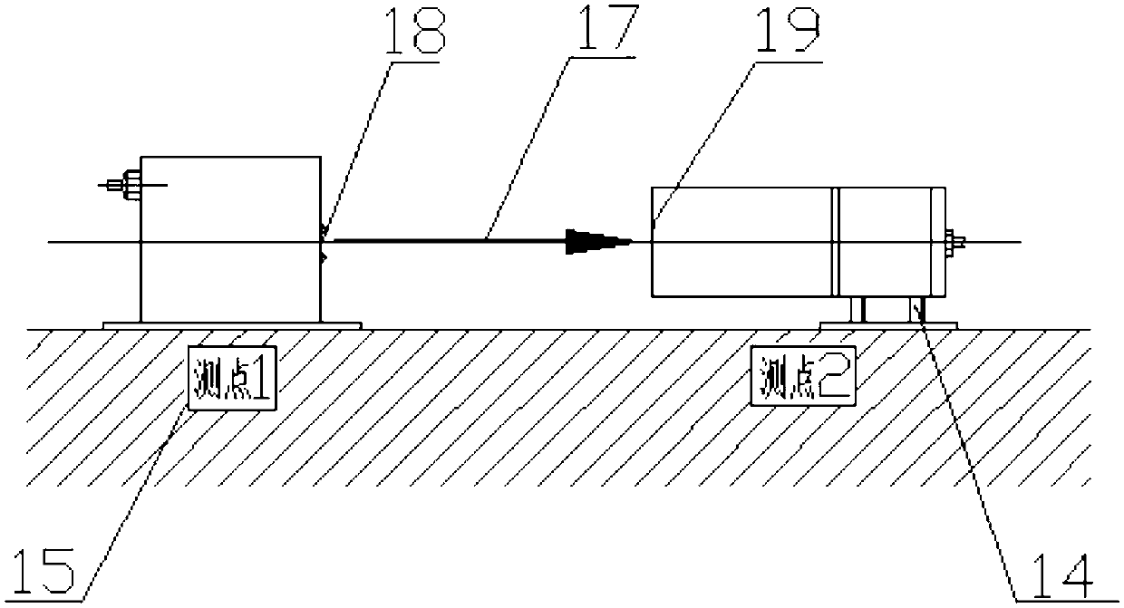
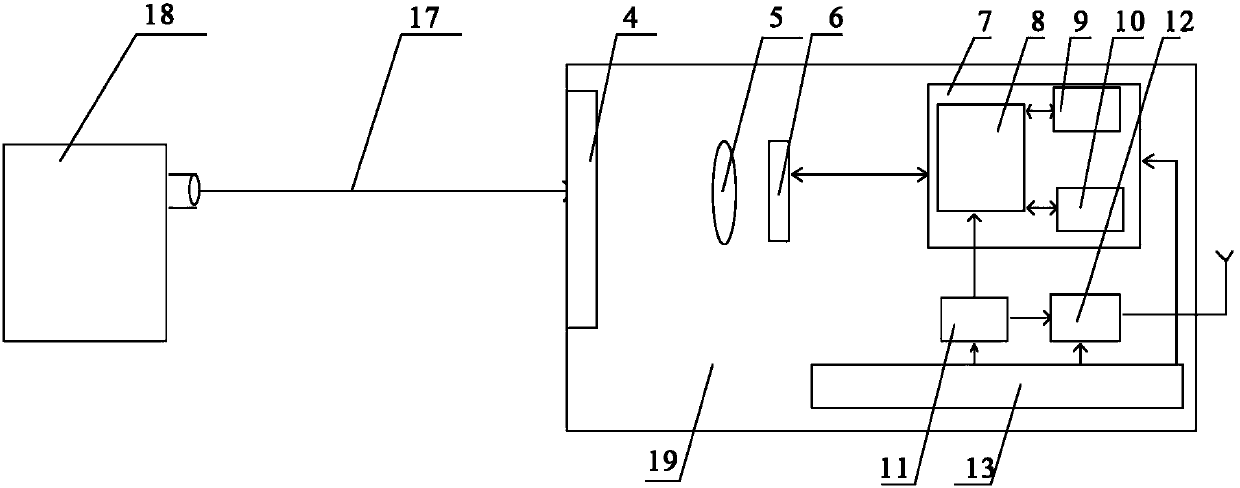
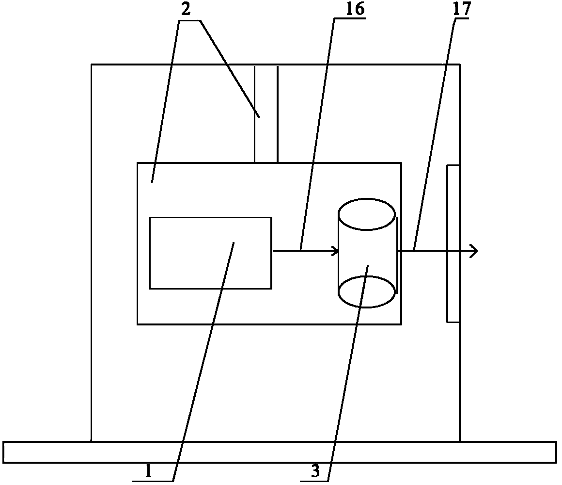
[0031] Such as figure 1 and figure 2 As shown, the high-speed iron differential settlement monitor of the present invention includes a transmitting module 18 and a receiving module 19; see image 3 , in this embodiment, the transmitting module 18 includes a semiconductor laser 1 and an optical conversion lens, the semiconductor laser 1 and the optical conversion lens are suspended and installed through the suspension assembly 2, and the optical conversion lens can be a cylindrical mirror 3. The high-performance semiconductor laser 1 (such as a point laser) used in the transmitting module 18 emits a laser beam 16 (such as a point laser beam), and the laser beam 16 is converted into a line laser beam 17 after passing through a cylindrical mirror 3 for transmission , so that the laser beam 16 is projected on the receiving board 4 at t...


PUM


Abstract

The invention discloses a differential settlement monitoring instrument for a high-speed rail. The differential settlement monitoring instrument comprises a transmitting module and a receiving module which are respectively arranged on two measuring points, wherein the transmitting module comprises a semiconductor laser device and an optical conversion lens; the receiving module comprises a receiving plate, an imaging system, a line array complementary metal oxide semiconductor (CMOS) image sensor, a micro processor system and a network interface component, wherein a laser beam transmitted by the semiconductor laser device is converted into a horizontal-line-shaped laser beam for transmission by the optical conversion lens; and the receiving plate receives the horizontal-line-shaped laser beam and transmits the horizontal-line-shaped laser beam to the micro processor system for analysis and judgment through the imaging system and the line array CMOS image sensor to obtain a settlement value. The differential settlement monitoring instrument is simple and small in structure, low in cost and easy to mount and debug, works stably and reliably and is suitable for long-time engineering monitoring.

Description

technical field [0001] The invention mainly relates to the field of engineering quality testing equipment, in particular to a monitor suitable for differential settlement of high-speed rail. Background technique [0002] As the state has increased investment in infrastructure construction in recent years, my country's high-speed rail construction has achieved rapid development. Due to the high speed of the train and high safety requirements, the high-speed rail project has more stringent requirements on the roadbed than the construction of roads, bridges and ordinary railways. Generally, the settlement cannot exceed a few millimeters, otherwise it will directly affect the safe operation of the high-speed rail. into a serious disaster. [0003] In the prior art, a liquid level-type settlement deflection detection system connected with an electronic level is a relatively widely used settlement monitoring method at present. The connected liquid level settlement deflection det...

Claims


Application Information

Patent Timeline
Patent Type & Authority Applications(China)
IPC IPC(8): G01C5/00
Inventor 魏丽敏何群曹龙周广
Owner CENT SOUTH UNIV
Learn More