

Micro sample creep and creep fatigue test system and test method
A creep fatigue test and micro-specimen technology, applied in the creep fatigue test system and micro-specimen creep field, can solve the problem of inability to take into account the micro-tensile specimen creep test and the micro-bending specimen creep test, etc. , to achieve the effect of promoting
- Summary
- Abstract
- Description
- Claims
- Application Information
AI Technical Summary
Problems solved by technology
Method used
Image

Examples
Embodiment 1
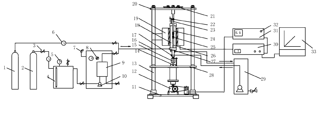
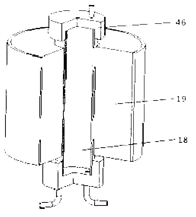
[0058] Such as figure 1 As shown, the micro-sample creep and creep fatigue test system of the present invention include a gas cylinder 1, a nitrogen cylinder 2, a valve 3, a water tank 4, a pressure gauge 5, a flow meter 6, a safety valve 7, a switch 8, and a steam generator Device 9, water pump 10, base 11, AC servo motor 12, column 13, distance sensor 14, force sensor 15, main frame 16, cooling system 17, quartz tube 18, high temperature furnace 19, upper beam 20, locking device 21, pin 22, upper support rod 23, clamping mechanism 24, clamp kit 25, lower support rod 26, air inlet 27, middle beam 28, cooling water 29, temperature controller 30, equipment controller 31, emergency stop switch 32, computer 33.
[0059] The main frame 16 is composed of a base 11, an upper beam 20, a middle beam 28 and two columns 13; the lower end of the AC servo motor 12 is fixed on the base 11, the upper end passes through the middle beam 28, and the AC servo motor 12 drives the reducer throug...
Embodiment 2
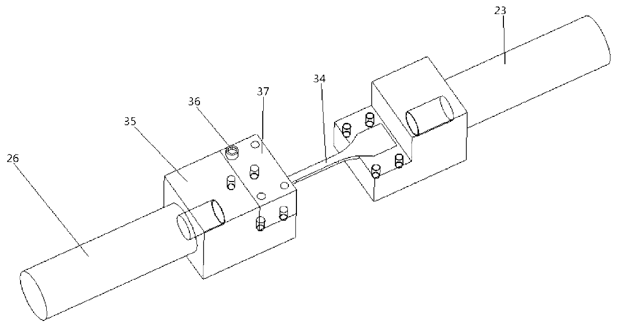
[0064] Such as image 3 As shown, the clamp kit 25 of the present embodiment includes a front mold 37 and a rear mold 35, the front and rear molds are connected by hexagon socket bolts 36, the rear mold 35 is connected with the lower support rod 26 or the upper support rod 23 by threads, and the micro-tensile sample 34 Place it in the groove of the rear mold 35 and fix it by the shoulder of the micro-tensile sample 34; the high-temperature furnace 19 is a split vertical high-temperature furnace. After the temperature is measured by the thermocouple attached to the fixture suite 25 in the quartz tube 18, it is regulated by the temperature controller. The high-temperature furnace 19 is connected with the temperature controller 30 with wires, and the thermocouple is connected with the temperature controller 30. The high-temperature furnace 19 is fixed on On the column 13 of the main frame 16.
[0065] The steps that present embodiment carries out micro-tensile sample test are as...
Embodiment 3
[0075] Such as Figure 4 Shown is the fixture set 25 of this embodiment, the fixture set 25 is a three-point bending fixture set, which can realize the theoretical model of three-point bending, has high precision, and can fully contact with the ambient gas, such as Figure 4 As shown, it includes a positioning sleeve 41 , a single head pressing rod 40 and a base 38 . Wherein, the upper support rod is embedded in the upper end of the quartz tube, and is threadedly connected with the single-head pressure rod 40; the lower support rod is embedded in the lower end of the quartz tube, and is threadedly connected with the base 38, two Cylindrical rollers 39 are embedded on the base 38 to form two fulcrums of the sample, and the base 38 is partially hollowed out between the two cylindrical rollers 39 to facilitate deformation of the sample. The microbending sample 42 is placed on the cylindrical roller 39, and the two ends are embedded in the fixture by about 0.5 mm, and fixed by dr...
PUM
 Abstract
Description
Claims
Application Information